Posts

Showing posts from December, 2018

Universal Component Tester

Image
  Universal Component Tester Filed in Universal Component Tester on Dec.31, 2018 While cleaning up some shelves in the shop last week, I came across one of those cheap little component testers that I bought from some forgotten vendor in the past.  These are pretty convenient to identify unknown components and do a simple functionality test of all kinds of components.     Universal Component Tester It came unmounted to anything, so I decided to stick it into a small metal box to protect it from dirt and dust as it sits on a shelf between uses.  I have a stack of 24 little metal boxes that I bought surplus from another forgotten vendor.  They are brand new, never used.  A little bit bigger than a typical Altoids tin, but made out of the same thin metal. The back of the boxes shows that they were intended to package some tobacco product.  But again, they were never used, so no smell associated with them. I guess they could be considered the modern day equivalent of the old

Electronic Key Interface for Vintage Rigs

Image
  Electronic Key Interface for Vintage Rigs Filed in Vintage Radio on Dec.30, 2018 Sometime this past year, I acquired a Jackson Harbor Press KeyallHV kit.  This accessory allows one to key their vintage rig, be it an old tube rig, a hybrid or a more modern solid state one.  It is basically a circuit that isolates the keying contacts from any high voltage circuitry in the rig via an opto-isolator and a set of heavy duty MOSFETS.     Kit assembled While I like CW operation (especially for contests), and I can copy code at 15 wpm without too much problem, I am a big fan of paddles and keyers of any type that eases the sending of CW.  This includes using a computer to send canned messages typical for a contest contact. A straight key is OK, but I like the modern conveniences for this. For example, I use the N3FJP log on my computer to log all contacts in contests and for awards.  It has a built in keyer that uses one of the lines of the serial port of the computer to key a

Heathkit TC-1 Tube Checker - Theory of Operation - Quality Check

Image
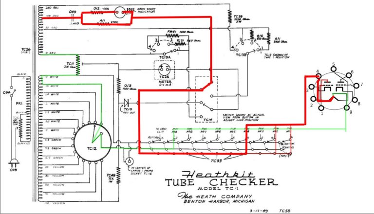
  Heathkit TC-1 Tube Checker Theory of Operation - Quality Check Filed in Heathkit TC-1 on Dec.21, 2018 The Quality Check is the main function of the TC-1 Tube Checker.  In this mode, the tube is connected into the circuit to act as a simple diode.  No effort is made to find how much gain a given tube might have in other configurations.  This is a very basic test of how well the tube emits electrons from its cathode and transfers them to the plate of the tube. In the diagram below, the Red circuit is the plate supply circuit, typically 30 Vac, except for gas regulator tubes, which use the 250 volt winding of the transformer.  With the bank of 10 switches, each switch is connected to a different pin of the tube under test.  Switch A = Pin 1, Switch B = Pin 2, etc…  Switches are set according to the roll chart for a specific tube type.     TC-1 Quality Check So all tube pins set to the top position are connected to the same electrical point, which has the plate supply volt

Heathkit TC-1 Tube Checker – Theory of Operation – Filament Check

Image
  Heathkit TC-1 Tube Checker – Theory of Operation – Filament Check Filed in Heathkit TC-1 on Dec.21, 2018 The TC-1 uses a neon bulb to sense relatively higher current flow in the plate circuit of the tube under test.  It uses this function in order to detect short circuits between the various elements of the tube. It uses this same circuitry to test whether a filament has continuity or is open.  To set up the test, the tube tester is set to connect the plate and grids of the tube under test together and connect them to a 100vac source.  The cathode and one side of the active filament are connected to the low side of the source transformer (o volt of the filament winding).  The other side of the filament under test is connected to the appropriate filament voltage winding (i.e. 6.3 volts).  This is the “normal” starting settings for testing the tube. The neon lamp does not light, because the current through the vacuum of the tube is not high enough to cause it to light.

Heathkit TC-1 Tube Checker – Theory of Operation – Line Set Mode

Image
  Heathkit TC-1 Tube Checker – Theory of Operation – Line Set Mode Filed in Heathkit TC-1 on Dec.21, 2018 Theory of Operation: Line Set Mode In Line Set Mode, the TC-1 is set up to measure the 115 volt winding of the transformer, and set it to 115 volts, regardless of a variation in the line input voltage.  This allows the checker to give valid go/no-go checks of tube emissions even if the line voltage is above or below the nominal 115 volt line voltage.     TC-1 Line Set Circuit To make this reading, the circuit is set to read the voltage from the 115 volt winding, through the 75K ohm resistor TC49, the 1200 ohm resistor 012 (in parallel with the meter and diode string), and a portion of the Plate control TC11. Because the 75K ohm resistor is so much larger than the other resistances, it pretty much sets the current through the circuit at about 1.5ma. The Plate control varies between 0 and 200 ohms, but does not really affect the reading because the 75K ohm resistor do

Heathkit TC-1 Tube Tester Restoration Part 10

Image
  Heathkit TC-1 Tube Tester Restoration Part 10 Filed in Heathkit TC-1 on Dec.20, 2018 Part 10: Operational Testing With the TC-1 Tube Checker electrical restoration complete, it was time to run through a few tubes to see how it works… Step 1 : Set all controls for startup. Set Line – Center Range Type – 1 Filament – 0.75 Plate 0   Initial Settings Step 2 : Pick a tube – This is a 12AU7A   12AU7A Step 3 : Look up the settings in the roll chart, or supplemental documentation (there are several out there on the internet, listing tubes that did’t exist when this tube tester was designed. 12AU7 has two sections to test, so two lines of data First section – Type = 2, Filament = 6.3, Plate = 25, Top = AB, Bottom = CDE Note that Switches D & E are bold – these are filament pins on the tube   Roll Chart Step 4 : Set the switches to match the chart   Switches for 12AU7 Each of the controls are set according to the roll chart entry.  The switches marked TOP are raised to the up

Heathkit TC-1 Tube Tester Restoration Part 9

Image
  Heathkit TC-1 Tube Tester Restoration Part 9 Filed in Heathkit TC-1 on Dec.20, 2018 Part 9: Cabinet Restoration The cabinet was a little beat up, but not in too bad of condition mechanically.     Cabinet start condition Cabinet restoration began with sanding the wood to remove the old varnish, and remove the majority of the chips, nicks, etc.  After sanding, I put it on the bench and applied a coat of stain/polyurethane finish to all surfaces.     Selected Finish     First Coat Applied After the first coat, I buffed it down a bit with steel wool, then applied a second coat. After the second coat, I buffed it down with steel wool again, and mounted the panel into the cabinet.  It looks a little better, I think…     Left Side   Right Side     Top

Heathkit TC-1 Tube Tester Restoration Part 8

Image
  Heathkit TC-1 Tube Tester Restoration Part 8 Filed in Heathkit TC-1 on Dec.18, 2018 Part 8: Initial Testing The moment of truth has arrived.  Will it thrive, or go up in smoke?? I plugged the newly reassembled TC-1 into my variac to bring up the voltage slowly.  Before powering on the unit, I put the controls in the following positions: Set Line: Full CCW Filament Voltage: 0.75v Lever switches: All in center position Type: 1 Plate: 0 % Then, I turned on the tube checker.  As I raised the voltage, there were no signs of obvious electrical problems, and the Line Voltage indicator slowly crept up. I found that I could center the Line Level on the meter at any voltage between 107 and 130 vac line voltage. I checked various filament voltages.  With the Line Level centered in the meter, I found that they were all around 10% higher that what was marked.  This is not too far off from the state it had arrived in, where filament voltages were high at that time, too.  But I figur

Heathkit TC-1 Tube Tester Restoration Part 7

Image
  Heathkit TC-1 Tube Tester Restoration Part 7 Filed in Heathkit TC-1 on Dec.18, 2018 Part 7: Reassembly – Panel Wiring It’s time to install the wiring harnesses that we made a few days ago onto the panel.  I started with the harness that runs from the 10 lever switches to the tube sockets on the top left of the panel (as viewed from the back).     Lever Switches Wiring With the wire colors I had available, I tried to follow a color code like the resistor color code.  i.e. pin1 = brown, pin 2 = red, etc…  I had to fudge with a few colors, but it made wiring the panel much easier than if they were all the same color, or random colors.  The first switch on the left is wired to all of the tubes pin #1 locations in a daisy chain.  The second switch (with the red wire) is connected to all of the tubes pin #2 locations, and so on through switch # 9. Switch #10 on the right side is wired to the extendable grid cap.     Tube Socket wiring from lever switches. When the firs

Heathkit TC-1 Tube Tester Restoration Part 6

Image
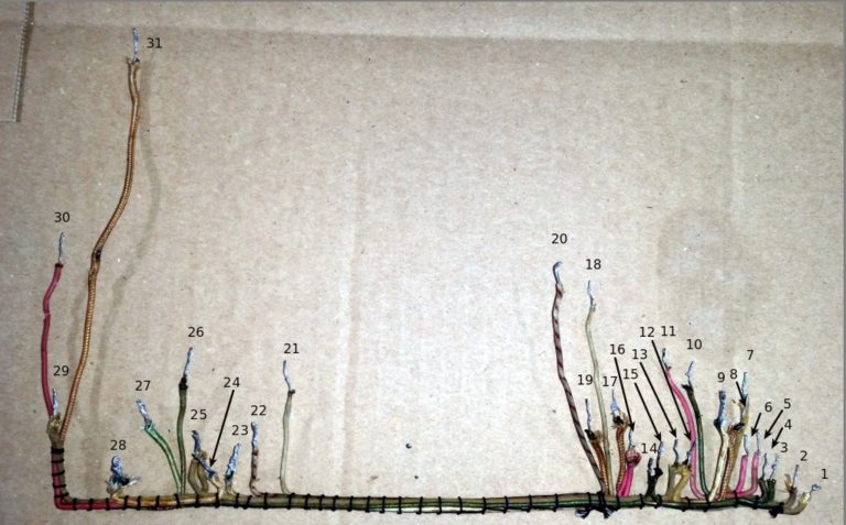
  Heathkit TC-1 Tube Tester Restoration Part 6 Filed in Heathkit TC-1 on Dec.13, 2018 Part 6: Reassembly Con’t… Wiring Harnesses The instructions for assembly in the TC-1 manual leave a lot to be desired.  It is one long, run-on sentence/paragraph that tells you generally what to hook up in sequence.  This was before Heathkit came up with its standard “check the box” format that they became famous for. After looking at the TC-2 manual, I find that there is little difference between the TC-1 and the TC-2.  Since the TC-2 has a much better manual, that is what I will generally follow while reassembling the tube checker. After assembling the major pieces to the front panel in the previous ( Part 5 ) post, the next step is to rebuild the two wiring harnesses.  The originals have insulation crumbling, and are no longer reliable nor safe.     Top Wiring Harness (old) One harness is used to connect the row of wafer switches along the bottom of the tube tester with the tube soc