Heathkit TC-1 Tube Tester Restoration Part 10
Heathkit TC-1 Tube Tester Restoration Part 10
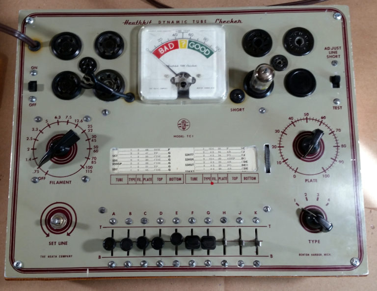
Part 10: Operational Testing
With the TC-1 Tube Checker electrical restoration complete, it was time to run through a few tubes to see how it works…
Step 1: Set all controls for startup.
- Set Line – Center Range
- Type – 1
- Filament – 0.75
- Plate 0
Step 2: Pick a tube – This is a 12AU7A

Step 3: Look up the settings in the roll chart, or supplemental documentation (there are several out there on the internet, listing tubes that did’t exist when this tube tester was designed.
- 12AU7 has two sections to test, so two lines of data
- First section – Type = 2, Filament = 6.3, Plate = 25, Top = AB, Bottom = CDE
Note that Switches D & E are bold – these are filament pins on the tube

Step 4: Set the switches to match the chart
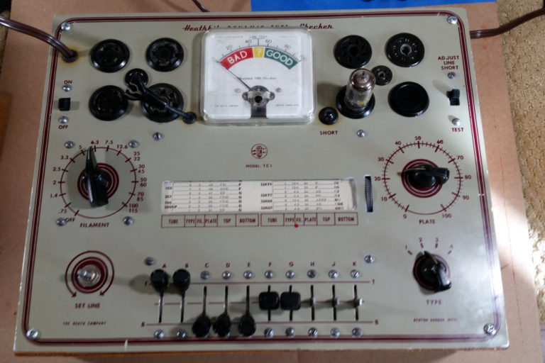
Each of the controls are set according to the roll chart entry. The switches marked TOP are raised to the upper position, the ones marked BOT are lowered to the lower position. All others are left in the middle.
Note that in the real world, A = Pin 1 of the tube, B= Pin 2, C = Pin 3, etc…
Step 5: Adjust the Set Line to center the meter.

Step 6: Check for shorts by moving any switches that are in light type in the chart to the opposite position (TOP –> Bottom, Bottom –> Top) (ONE at a time…) If there is a short, the neon light will glow. Return the switch to the original position before moving on to the next one. We would check switch A, then switch B, then switch C in this case.

Step 7: Check for good filament –
- Set the Filament voltage to .75
- Move the switches in Bold to their opposite position (ONE at a time).
- The neon light will glow if the filament checks good. Return the switch to the original position, and check the next switch.
- Return the Filament Voltage to the original position (6.3 volts in this case).

Step 8: Check tube emission by pressing the Test Switch to the lower position (It is spring loaded). If the tube is good, the meter will read in the “GOOD” range.

Step 9: While holding the Test switch in the TEST position, check for open elements by moving each lever in the TOP position (only those in light type) to the bottom.The meter should drop by some amount. Sometimes a lot, sometimes a little. If it doesn’t drop, that may indicate an open element in the tube.
Repeat steps 3 – 9 for the next line of data, if the tube type lists multiple lines.
That’s pretty much it. Seems to work ok. Now I just need to find or make some knobs/switch caps.


Comments
Post a Comment