Posts

Showing posts from January, 2018

Tektronix 2465A Oscilloscope Repair - Part 13

Image
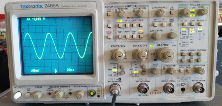
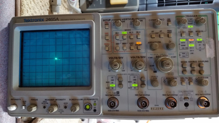
  Tektronix 2465A Oscilloscope Repair - Part 13 Filed in Tektronix 2465A on Jan.29, 2018 Dynamic Centering, DC Balance and X-Y Phase Differential I got in a hurry and forgot to get photos of this procedure.  But all went as described in the manual. Dynamic_Centering.PDF   All Done! The first step involve inputting a 5 division 6-Mhz sine wave to the scope with the settings as described in the manual. I moved the intensity control full CCW to Full CW, back and forth, looking for any shifting of the display.  There was none that I could see. If there had been, I could have adjusted R3401 and R3407 to minimize it. In Step 2, R618 may be adjusted for minimum vertical readout jitter with a full scale pulse waveform present.  I was able to tweak the adjustment to create jitter in the readout, and adjust it back to stable. Similarly, with the scope in x10 mode, and Delta-T cursors displayed, R805 could be adjusted for minimum horizontal jitter of the readout characters. In st

Tektronix 2465A Oscilloscope Repair - Part 12

Image
  Tektronix 2465A Oscilloscope Repair - Part 12 Filed in Tektronix 2465A on Jan.29, 2018 CAL07 – Readout Centering and Gain CAL07.PDF We are near the end of the poor man’s calibration of the 2465A Oscilloscope. CAL07 adjust the position of the Readout characters on the screen.  They are simply moved with two controls (R2918 and R2931) to place them just inside of the graticle area of the screen.   CAL07 – Readout Centering and Gain The adjustments are on the small card accessed from the top of the scope opposite the CRT.   Readout Position Adjustment Location     Readout Position Controls Close Up Once the display is centered, it is time to move the CAL Jumper back to the “NO CAL” position. The second half of this procedure seems to be adjusting the Limited Bandwidth parameters with the 20 Mhz Bandwidth Limit turned ON. The adjustment is coil L644.   L644 Location     L644 Close Up I simply applied a 100 Khz, 5 division square wave and adjusted for the flattest waveform.  N

Tektronix 2465A Oscilloscope Repair - Part 11

Image
  Tektronix 2465A Oscilloscope Repair - Part 11 Filed in Tektronix 2465A on Jan.28, 2018 CAL 06 – Vertical Transient Response Now comes the most difficult part of the calibration – The Vertical Transient Response. The goal of this procedure is to end up with a scope that is relatively flat across its bandwidth.  It uses a very fast rise time pulse to make the adjustment, and I just do not have one available. When I first checked the bandwidth, it fell off drastically at 8 Mhz, and was nearly unusable at 350 Mhz.  There were several significant dips and peaks as I swept the input sine wave from 1 Mhz to 350 Mhz, and I hoped that these would be corrected when I finished. Steps a – c start up the procedure.   CAL06 – Start Steps d – f cover setting up the pulse to channel 1.  I used the fastest rise time pulse I could find in my shop, and still had a 40ns rise time – way too long to be very effective.  I did have a 10db attenuator that I threw in line, but it made no differ

Tektronix 2465A Oscilloscope Repair - Part 10

Image
  Tektronix 2465A Oscilloscope Repair - Part 10 Filed in Tektronix 2465A on Jan.28, 2018 CAL 05 – Hours ON and PWR ON/OFF Cycles This routine simply allowed me to set the Hours and Power cycles to whatever number I wanted.   CAL05 – Start Steps a – d start the procedure and reset the Hours and Cycles to zero.  I didn’t bother changing them to some random number, because it would have no meaning in a 30 year old scope.  I just left them at zero and exited the routine.   CAL05 – Hours and Cycles

Tektronix 2465A Oscilloscope Repair – Part 9

Image
Tektronix 2465A Oscilloscope Repair – Part 9 Filed in Tektronix 2465A on Jan.28, 2018 CAL04 – Ch 2 Delay Enable/Disable For this section, I am simply enabling the Channel 2 Delay function and checking functionality with it enabled.  I could choose to leave it enabled, or to disable it.  I left mine enabled.   CAL04 Start Steps a – d start up the procedure and allowed me to flip back and forth between CH 2 Delay Enabled and Disabled.  After selecting “Enabled” I pressed the A/B Trig button to leave the function.   CAL04 Disabled     CAL04 Enabled In steps e – f, I set up a narrow pulse at 100 Khz.  Since I do not have a Calibration Generator, I used the pulse output from my Agilent scope’s function generator.  It’s not a terribly fast rise time, but seems to work for this check. The procedure calls for using a dual-input coupler, which I do not have.  I simply used a BNC T to feed both channels with identical length RG-58 cables. In step g – i, I set the generator to creat

Tektronix 2465A Oscilloscope Repair – Part 8

  Tektronix 2465A Oscilloscope Repair – Part 8 Filed in Tektronix 2465A on Jan.27, 2018 CAL 03 – Triggering The purpose of this section is to set the triggering levels for the 4 channels of the scope. CAL03.PDF I didn’t capture photos of this, as it went by so fast, I forget to get snapshots.  But all that showed was the normal display of Channel #, Input Voltage and Step number.  There were no waveforms displayed. The scope automatically runs steps 201 – 214 when you start the procedure. Then in steps d – g, you are inputting a 500mv square wave to channel 1 and stepping through steps 215 and 216. Steps h – k uses a 500mv square wave to Channel 2 to step through step 217. Steps l – m uses a 500mv square wave to Channel 3 for step 218. Steps n – o uses a 2 volt square wave to Channel 3 for step 219. Steps p – q uses a 500mv square wave to Channel 4 for step 220. Steps r – s uses a 2 volt square wave to Channel 4 for step 221. It was all very straight forward…  

Tektronix 2465A Oscilloscope Repair – Part 7

Image
  Tektronix 2465A Oscilloscope Repair – Part 7 Filed in Tektronix 2465A on Jan.27, 2018 CAL 02 – Vertical Adjustments The purpose of this adjustment it to set the calibration parameters for the vertical gain of the scope at the various input voltage ranges. CAL02.PDF   CAL02 Start On starting the CAL02 procedure, it automatically runs through some internal tests, incrementing the step counter from 100 – 110, stopping at step 111.   CAL02-111 At this point, you are prompted to input various “Standard Amplitude Signals” into the Channel 1 or Channel 2 input BNC connectors. From my research, it appears that “Standard Amplitude” means a square wave at 50% duty cycle, at 1Khz frequency. The amplitude is set at the generator to match the requirements in the instructions. In steps CAL02 e – g, you are inputting a 500mv, 1Khz square wave to channel 1 and using the Channel 2 position to move the two displayed dots up and down to align them with the center graticle. Then you use

Tektronix 2465A Oscilloscope Repair – Part 6

Image
  Tektronix 2465A Oscilloscope Repair – Part 6 Filed in Tektronix 2465A on Jan.26, 2018 Continuing on with our CAL 01 steps… Step 2 – 6: Adjust timing markers for different sweep speeds There are more timing adjustments in steps p – r. This time you are highlighting the 2nd and 10th markers, and overlapping the pulses.   CAL 01-r Steps s – u are setting up a slower sweep, highlighting the 4th and 28th markers, and overlapping the pulses.   CAL 01-u Steps v – x are a little different. You line up a marker on the left graticle, then use the Delta control to move the second marker where the first was at. Sorry for the blurry photos…   CAL 01-w Steps y – aa appear to be setting up the x10 gain. You position the two cursors on the 2nd and 10th graticles, using the x1 gain control, then use the x10 gain control to set 10 markers in that space.   CAL 01-aa Steps bb – dd work just like steps p – r. Steps 7 -16: More Timing adjustments Steps ee – ff runs you through a table of differ

Tektronix 2465A Oscilloscope Repair - Part 5

Image
  Tektronix 2465A Oscilloscope Repair - Part 5 Filed in Tektronix 2465A on Jan.26, 2018 CAL 01 – Horizontal CAL01.PDF Now that the basic power supply and CRT display are set up, we can continue with the meat of the calibration. It is suggested that all of the CAL xx steps be run in order, in the same session.  I tried to split it up, and it seemed to not store my results between sessions (even with my new lithium battery).  When I ran them all in the same session, the calibration factors were all stored and remain through power cycles now. First, you must put the CAL ON/OFF jumper into the CAL ON position.  This is on the A5 Controller board.   CAL Jumper Step 1 – Horizontal Timing, X1 Gain, X10 Gain, Center, Transient Response Following the detailed instructions 1a – 1c will put you into the CAL 01 function.   1b – Begin Calibration     1c – CAL 01 Steps 1d – 1g connects the scope probe to an internal test point on the scope (R489).   R489 Location   R489 Test Point   CAL

Tektronix 2465A Oscilloscope Repair – Part 4

Image
  Tektronix 2465A Oscilloscope Repair – Part 4 Filed in Tektronix 2465A on Jan.26, 2018 CRT Screen Adjustments After the initial Low Voltage Power Supply adjustments, the next step is to run through the CRT screen adjustments. I was thrown off here at first by the order that the adjustments show up in the manual. The manual starts off the Adjustments section with an Introduction, followed by a Power Supply procedure. It then continues with CRT Adjustments, but for the 2467 scope with serial numbers B011012 and up. This is not the section I needed, as my scope is a 2465A with a low serial number. Here is the order of the manual, with the sections for my scope highlighted and numbered in the order I used. Lesson – Pay attention to your particular model number and serial number… Power Supplies (01) 2467 CRT Adjustments – Serial Number B011012 and Up 2465A CRT Adjustments – Serial Number B014331 and Up CAL 01 – Horizontal (03) CAL 02 – Vertical (04) CAL 03 – Triggering (0