Posts

Showing posts from February, 2009

MMR40 L1/L2 Connections

Image
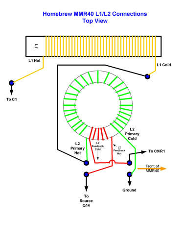
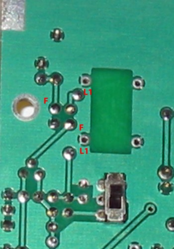
  MMR40 L1/L2 Connections Filed in Kits on Feb.25, 2009 One of the members of the MMR40 Yahoo Group is having difficulty getting his MMR40 PTO to oscillate. We had worked out how to wind the L2 coil, based on the pads of the Homebrew version being different than the pads of the Kit version. We didn't look close enough at the feedback winding pads, though. In the Homebrew version, it appears that you have to swap the ends of the feedback winding , in order to keep the feedback in phase with the main winding. Here is how I think the feedback winding needs to be connected for the homebrew version: L1/L2 connections for Homebrew PCB As opposed to the way L2 is connected for the Kit version of the PCB: L1/L2 Connections for Kit PCB The thing to watch is that the windings have a hot end and a cold end. If you start at the hot end of a winding, the other end is obviously the cold end. If you connect a second coil in series, off of the cold end of the first, as we do here,

MMR40 U3 LM386 Waveforms

Image
  MMR40 U3 LM386 Waveforms Filed in Kits on Feb.21, 2009 In an attempt to help others that may be having problems in the audio stages of their MMR40, here are some waveforms and DC/AC voltages for the final audio amplifier stage U3. All measurements are with volume control V2 full on, sidetone level control V5 full on, and with switch S1 in the wide position. In general, you should be able to touch the input to U3 on pin 2 with your finger (or hold an uninsulated piece of wire to U3-2 with your fingers), and hear a 50 or 60 hz audio hum from the speaker from what you pick up around your house. If you cannot hear this hum, there may be something wrong in the audio stages, particularly U3. There is a second source of audio available on board, in the form of the sidetone oscillator that feeds into U3 pin 3 via the sidetone oscillator level control V5. To enable this tone (at least in the kit version) you must set the rig to CW mode my shorting the Microphone Jack Sleeve to

MMR40 – Kit vs Homebrew L2

Image
  MMR40 – Kit vs Homebrew L2 Filed in Kits on Feb.09, 2009 After more comments on the MMR40 Yahoo Group, it is once again apparent that there are some significant differences between the Kit PCB and the Homebrew PCB pattern. This time, the winding of the L2 PTO coil is affected. Here is the bottom of my Kit PCB: MMR40 Kit PCB Bottom View L2 Pads And here is the same image, but flipped over so as to see through the board from the top side. This puts the PTO circuit in the upper right, as the Layout diagram is oriented. MMR40 PCB Flipped L2 Pads And here is the Layout drawing in the Kit Documentation: MMR40 Kit Layout L2 Placement From all of this, it is apparent that The Top of L1 (Near the screw) connects to the Upper Left of the 4 pads used for L2, as viewed from the parts side of the board. The Bottom Of L1 connects to C8. The Top Right Pad of L2 (Marked with an F) connects to R1 and C9. The Bottom Left Pad of L2 connects to Q14. The Bottom Right Pad o

MMR40 First Mixer Analysis

Image
  MMR40 First Mixer Analysis Filed in Kits on Feb.08, 2009 The first Mixer is used to develop the 10 MHz IF in receive, or the 7 MHz final frequency in transmit. On Transmit, the PTO output is mixed with the 10 Mhz Transmit IF signal to create the 7 MHz output signal. On Receive, the PTO output is mixed with the incoming 7mhz Receive signal to create the 10 MHz receive intermediate frequency. MMR40 First Mixer U6 Stage The first mixer in the MMR40 is a SA612 double-balanced mixer. The datasheet can be downloaded from the Phillips Site. Pin 1 and Pin 2 are signal inputs Pin 3 is ground Pin 4 and Pin 5 are mixer outputs Pin 6 and Pin 7 are the Oscillator inputs Pin 8 is VCC (4.5 to 8 vdc) SA612 Block Diagram The 5 volts VCC voltage is supplied by U2, a 7805 3-terminal regulator. U2 also supplies the other SA612 mixer further down the line. On receive, the 40-meter input signal is coupled through the DC blocking capacitor C16 to pin 1. The 0.001uf capacitor has about 22 ohm

MMR40 L2 Winding Diagram

Image
  MMR40 L2 Winding Diagram Filed in Kits on Feb.08, 2009 This is how I wound the L2 toroid on my MMR40. I started with the green wire on the right side, as I look at the toroid. After winding 28 turns, I left a loop of an inch or so, and continued winding the turns that show in Red in the diagram. The Red turns are the feedback winding , and the green turns are the main or primary winding . Note how, once the loop is cut, the Red and Green wires are pretty much straight across from each other. That is how they fall into place onto the PC board. You shouldn't have to cross any wires, they just drop straight into the holes on the PC board. It doesn't look like it would make any difference if you turned the toroid 180 degrees, as the Feedback wires would still drop straight into the Feedback holes, and the main windings would still drop into the main holes. And since the main and Feedback windings would still be in phase, due to being wound in the same direction o

A Better Overlay for the MMR40 Homebrew PCB

Image
  A Better Overlay for the MMR40 Homebrew PCB Filed in Kits on Feb.07, 2009 Floyd, PD8F provided a link to an earlier version of the construction manual for the homebrew version. It has a much better overlay diagram than the one in my earlier post . So here is a copy of that diagram. It still won't line up 100%, but it comes pretty close.   Overlay diagram for the homebrew version of the MMR40     

MMR40_Kit vs Homebrew

Image
  MMR40_Kit vs Homebrew Filed in Kits on Feb.05, 2009 On the MMR40 Yahoo Group , there came a question concerning R24 and R30. Both are 1 Meg resistors, located close together. The confusion seems to stem from the fact that on the parts placement diagram, the two resistors are not labeled the same as on the schematic. This is true in both the Kit documentation and the ARRL Website Documentation. So, R30 on parts placement = R24 on schematic, and R24 on parts placement = R30 on schematic. The other problem brought up was that R30 (parts placement) had one end floating on the homebrew version of the PC board etching diagram (Available on the ARRL Website ). After tracing out the circuit, I believe that the floating end should be connected to ground. I have overlayed the homebrew PC board pattern with the parts placement, and marked the traces for each circuit. The R24 (Parts placement) is marked in Green. It should connect between the V5 potentiometer and C65. It appears