Posts

Showing posts from March, 2015

PCB Fabrication Experiments

Image
  PCB Fabrication Experiments Filed in homebrew on Mar.31, 2015 I’ve been reading a lot lately about making your own printed circuit boards (mostly on the yahoo group qrp-tech ) I have made PCBs before, but only with the photoresist method, which is fairly expensive. After witnessing the great results by Chuck, K7QO , and with him having done most of the legwork on the method, I decided to start experimenting with his method a bit.   First Attempt – Brother 5150d with plain paper The method involves using a laser printer to print a pattern on paper, then using a laminator to heat-transfer that pattern to the copper plated circuit board material. I had read that an HP printer works well, and had also heard about failures with the Brother brand of laser printers, due to the toner having a much higher melting point. Unfortunately, the Brother 5150d is the only laser printer that I have. But not to be discouraged, I decided to try it anyway, just to confirm that my aftermarket

8640 Jr. Power Connection

Image
  8640 Jr. Power Connection Filed in homebrew on Mar.31, 2015 OK… Last post on the 8640 Jr. I promise… I still needed to add a permanent power connection for the 12 volt supply to the 8640 Jr. I decided to use a couple of power poles mounted into the backplate.   Finished Power Pole and Fuse Holder Being inherently lazy, I used an existing hole, and just nibbled out the sides a bit so that the powerpole connectors kind of snapped into place. Then I used some JB-Weld to give them a little substance, so they wouldn’t pull out as I connected/disconnected the input.   Fuse Holder and Powerpoles in holes I found an old fuse holder and drilled out a hole to fit it. As I was working with it, the plastic broke right behind the mounting flange. A little JB-Weld here also fixed it right up.   Finished installation I decided to not put a power switch in, since this will not be plugged in all of the time. So I will just rely on unplugging it from the 12 volt supply when not in use.

8640 Jr Cabinet

Image
  8640 Jr Cabinet Filed in homebrew on Mar.15, 2015 For a cabinet, I chose an old surplus case from some old HP power supply. I made a new faceplate, and found a suitable way to mount all of the separate boxes that comprise the various stages of the 8640 Jr.   Finished Faceplate First, I replaced the nuts on the bottom of the modules with standoffs, to provide a way to secure them to a flat surface.   Mounting hardware for modules Next, I made a platform to mount some of the modules on, since there was not room to mount them on the same level. I used a piece of PC board for that purpose. Using some 1/2″ angle iron from the hardware store, I fastened it to the sides of the cabinet.     Modules mounted in cabinet Once the modules were mounted, I needed a way to get the shaft of the controls outside of the faceplate. I made couplings from some hardware purchased at ACE hardware.   Coupling To the front of these couplings, I attached lengths of 1/4″ round bar stock found at ACE,

8640 Jr Attenuator

Image
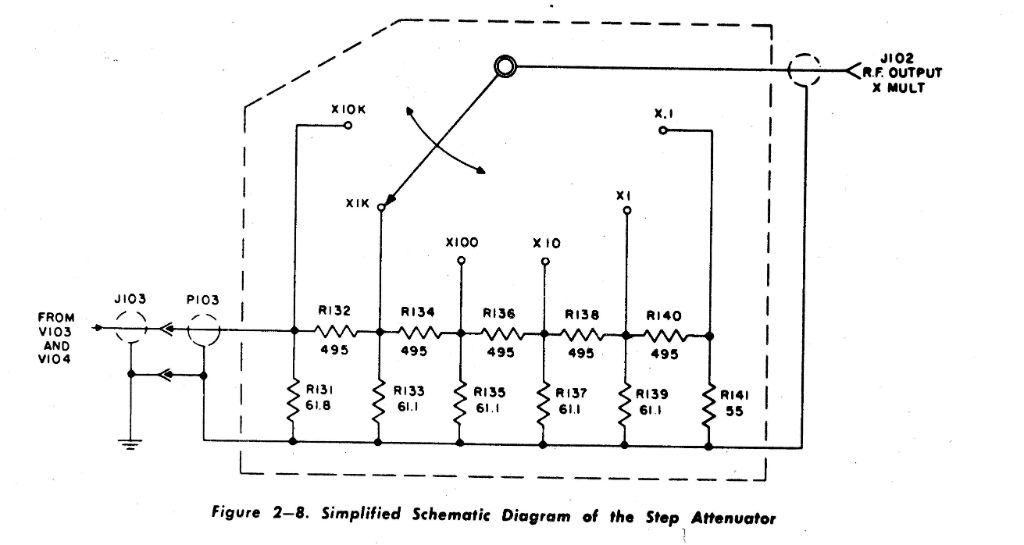
  8640 Jr Attenuator Filed in homebrew on Mar.15, 2015 Now that we have pretty good output on all bands, I wanted to be able to attenuate the signal to be able to use it for receiver testing. This required approximately 100 db of switchable attenuation. As a young Avionics Tech in the Marine Corps, I used an old tube-type signal generator called the URM-25d. The attenuator in it was adjustable in 20 db steps, so each step cut the signal voltage level by a factor of 10. I like that arrangement, and fancied myself doing something similar here.   URM-25d attenuator The URM-25d also had a fine attenuation control that let you dial the signal up or down between the x10 steps. So you could dial in precisely the signal level you wanted. The way the attenuator worked was that there was a metering circuit at the high level that was fairly easy to meter. So you would set the meter to a “Set” mark on the meter, which represented 2 volts RMS. Once that was set, the precision attenua

8640 Jr Revisited

Image
  8640 Jr Revisited Filed in homebrew on Mar.15, 2015 I’ve had this signal generator project on my bench for a while now. Basic functionality is there, with approximately +7dbm output from 833 kc to 36 mc or so. Now it’s time to put some finishing touches on it, and box it up in a presentable format. Band 1 covers 833 kc to 1.6 mc. Here is the output (all measurements into a 50 ohm load) The top yellow trace is the output for a frequency counter. The bottom Green trace is the high level output:     Band 1 Bottom ~833kc @ 6.5 dbm     Band 1 Top – ~ 1.6mc @ +1 dbm     Band 2 covers approximately 1.6 mc to 3.5 mc.     Band 2 Bottom – ~ 1.6mc @ +7 dbm   Band 2 Top ~ 3.5 mc @ +4 dbm   Band 3 covers approximately 3.5 mc to 6.6 mc.   Band 3 bottom ~ 3.3 mc @ +8 dbm         Band 3 Top ~ 6.6 mc @ +7 dbm   Band 4 covers approximately 6.6 mc to 12.5 mc.     Band 4 bottom ~ 6.6 mc @ +8 dbm   Band 4 Top ~ 12.5 mc @ +7 dbm Band 5 covers approximately 12.5 mc to 36 mc (extended by fine tunin