Posts

Showing posts from February, 2018

Heathkit IG-42 Laboratory Generator – Initial Checkout

Image
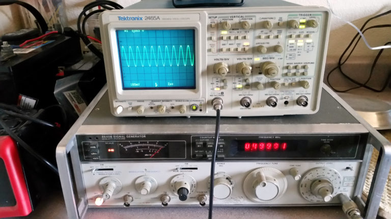
  Heathkit IG-42 Laboratory Generator – Initial Checkout Filed in Heathkit IG-42 on Feb.25, 2018 I hooked up the Heathkit IG-42 Signal Generator to the variac on the bench and brought the voltage up slowly, watching for signs of overheating or failed components.  There was a slight hum coming from the unit for the first couple of minutes, then it got better.  I suspect that the electrolytic capacitors were recovering after having not been in use for some time. The IG-42 is rated for 100,000 uv output, with a 50 ohm output impedance.  To check this against a known good source, I set up my HP 8640B signal generator for 0.1 volt output into the 50 ohm terminated input of my scope.  0.1 volt = 100,000 uv.   8640B Check Scope Calibration As the photo shows, I have about 0.28 vpp showing on the scope.  To get the rms value from the vpp value, you first divide by 2, then multiply by 0.707 0.28 / 2 = 0.14 0.14 x 0.707 = 0.09898  or approximately 0.1 vrms   8640B Output at 100,0

Heathkit IG-42 Laboratory Generator – First Look

Image
  Heathkit IG-42 Laboratory Generator – First Look Filed in Heathkit IG-42 on Feb.24, 2018 A friend and colleague of mine asked me to take a look at his Heathkit RF Signal Generator: IG-42.  The only information I got from him about it was that he had inherited it from a good friend, and had not had much luck using it. Here we will make our initial inspection of the unit, and try to get a feel for what work might be needed to restore it to a useful condition.   Front View as received The front panel is in pretty good shape, with just a few flaws: There is some writing or marks above the meter. There is a paint chip or scrape to the left of the frequency pointer. All of the controls are functioning, nut the knobs on some are loose.   Front Panel The cabinet has a pretty good sized dent on the top left side, and it is generally dirty and looks like it might have an oily residue on it.   Cabinet Top After pulling the cabinet off, we find that the chassis is a bit dirty on the

Heathkit C3 Condenser Checker – Wrapup

Image
  Heathkit C3 Condenser Checker – Wrapup Filed in C3 Capacitor Tester on Feb.24, 2018 Finally, I just wanted to demonstrate the operation of the C3 Condenser Checker.  I’m not much of a videographer, but here is my video demonstrating the device to check several good and bad capacitors for value and leakage. Enjoy!  

Heathkit C3 Condenser Checker - Knob Repair

Image
  Heathkit C3 Condenser Checker - Knob Repair Filed in C3 Capacitor Tester on Feb.24, 2018 Almost finished… A final repair on the knobs of the Heathkit C3 Condenser Checker, and it will be ready for operation.   Epoxy Two of the knobs had been overtightened in the past, and had cracked the knobs such that they could no longer be tightened enough to turn the controls.  Putting down a sheet of foil to control any mess on my bench, I used this two-part Epoxy from Harbor Freight to fill the holes around the outside of the knobs on the back. Hose clamps were tightened around the outside to force the knobs back together where they had separated at the cracks.  I left the center holes empty, so the shafts could still be inserted.   Knobs outside holes filled with epoxy After allowing the Epoxy to dry overnight, it became a very hard, clear filler.   Epoxy dried Then, I had no trouble tightening the knobs on the controls.  And they all still look original. They are the top right an

Heathkit C3 Condenser Checker – 25 Volt Mod

Image
  Heathkit C3 Condenser Checker – 25 Volt Mod Filed in C3 Capacitor Tester on Feb.11, 2018 As noted in my previous post, the 25 volt scale for the leakage test function of the Heathkit C3 Condenser Checker provided a voltage that was considerably higher than 25 volts.  It was closer to 50 volts.  This seems to be a design flaw, or a documentation flaw, as I don’t know which side of the team dropped the ball.  I chose to treat it as a design flaw, since the documentation and the front panel screen printing indicated that it should be a 25 volt scale.   25 Volt Mod in place To remedy this problem, I chose to modify the voltage divider in order to provide the 25 volt output, while keeping the rest of the voltage ranges pretty much the same as originally designed (they were all within 1 – 2% of spec, at modern line voltages). The 10k-ohm resistor at the top of the voltage divider is the one that is supposed to develop the 25 vdc for the 25 volt range.  The voltage divider