Heathkit TC-1 Tube Tester Restoration Part 7
Heathkit TC-1 Tube Tester Restoration Part 7
Part 7: Reassembly – Panel Wiring
It’s time to install the wiring harnesses that we made a few days ago onto the panel. I started with the harness that runs from the 10 lever switches to the tube sockets on the top left of the panel (as viewed from the back).

With the wire colors I had available, I tried to follow a color code like the resistor color code. i.e. pin1 = brown, pin 2 = red, etc… I had to fudge with a few colors, but it made wiring the panel much easier than if they were all the same color, or random colors. The first switch on the left is wired to all of the tubes pin #1 locations in a daisy chain. The second switch (with the red wire) is connected to all of the tubes pin #2 locations, and so on through switch # 9. Switch #10 on the right side is wired to the extendable grid cap.
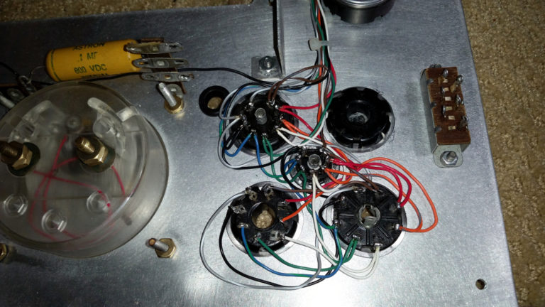
When the first harness was completed, I moved on to the second harness that runs along the top of the panel, extending the daisy chain wired tubes on the left to the right side of the panel. Again, All pin #1 are connected together, all pin # 2 are connected together, etc…

After checking connectivity from the switches to all of the corresponding pins on the tube sockets, I was able to mark the cable harnesses off my list.

Next, I began adding the various resistors in their proper locations. I had a bunch of 5%, 1-watt resistors from China on hand to replace most of them. The only three not replaced were the 75K ohm precision resistor, which measured perfect; the 360 ohm resistor, because China had sent me 330 ohm resistors in the 360 ohm package; and the 5-watt, 2500 ohm wire wound resistor, which was in good condition.
The 2500 ohm resistor was originally mounted on a two lug mounting strip, but it was too long, so was only connected to one lug, with the other end floating. I figured it would be best to have both ends solidly mounted, so I found a 4-lug strip that was long enough for the resistor to hit the two end lugs. I mounted this onto the left bracket for the roll chart, near the top, so as not to interfere with the chart workings or other electronics. Then I wired the 2500 ohm resistor to this, wrapping some wire around the lugs to hold it solidly in place before soldering it.
The roll chart was also on the list. I cleaned off as much of the old glue and tape as I could from the old acrylic window, using goo gone (the citrus kind) for most of the action. Then I glued it down to the back of the panel using Gorilla super glue, and holding it in place with black electricians tape.
Next, I added the roll chart into place. It was pretty fussy about how tight the roll was, as running it from one end to the other resulted in the rolls becoming very tight at each end. I balanced this out with how loose it was in the middle, and arrived at a compromise tightness that is working.
The remaining wires from the power transformer were connected as instructed in the manual (with me double-checking the pre-teardown photos to confirm locations as needed).
Adding the line cord completed the electrical construction.

Next up is the initial checkout. Stay tuned…


Awesome post. I would like to see the entirety of this restoration. Where can I find the other parts? Thanks.
ReplyDeleteIf you click on the (TC-1) link at the bottom of this post, it will list all of the posts for this restoration. I'm new to blogger, so I don't know how to sort them, but you can go through by the titles and read them in order. Good luck, and enjoy... Randy
ReplyDelete