Posts

Showing posts from January, 2009

MMR40 PTO Permeability Test

Image
  MMR40 PTO Permeability Test Filed in homebrew on Jan.25, 2009 With the components supplied with the MMR40 Kit, I cannot quite span the entire 40 Meter band. I was thinking that perhaps a different type of screw might cover more of the band. I’m only short about 25kc at the bottom, and 15kc at the top. So I went to the local Ace Hardware store to see what kind of #6 screws they have for sale. I found 4 varieties: brass, aluminum, stainless steel and an unmarked bin that I hoped was plain steel. After bringing the screws back, I set up an experiment: Find the edge of the spread without any screw in place. This turned out to be 2.839 Mhz on the CW segment, and 2.713 Mhz on the phone segment. The final frequency is 10.0 Mhz minus the PTO frequency, so these work out to be 7.161 Mhz for the upper CW segment Frequency, and 7.287 for the upper Phone Segment frequency. Take a voltage a frequency reading with the screw extracted Insert the screw under test all the way to its st

Analyzing the MMR40 PTO – Spice vs Real World

Image
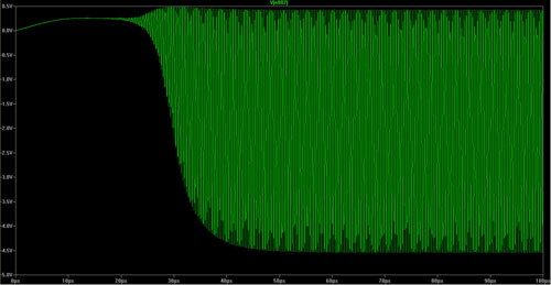
  Analyzing the MMR40 PTO – Spice vs Real World Filed in Kits on Jan.25, 2009 Some waveforms at startup from the spice model (Component designations from original manual, not spice model): J310 Gate (Q14): Q14 Oscillator Gate Startup ~ 5.0 vpp Scale: -5.0v to 0.5v Q14 Oscillator Gate ~ 5.0 vpp Scale: -5.0v to 1.2v And here is the measured waveform at Q14 Gate (Ac Coupled): Q14 Gate ~ 4.5 vpp (AC Coupled) And DC Coupled: Q14 Gate DC Coupled ~ 4.5vpp J310 Source (Q14): Q14 Oscillator Source Startup ~ 1.1vpp Scale: -0.1v to 1.2v J310 Source (Zoomed In): Q14 Oscillator Source ~ 0.5vpp Scale: 0.32v to 0.76v And the Measured Waveform: Q14 Source (AC Coupled) ~ 0.5vpp And DC Coupled: Q14 Source (DC Coupled) ~ 0.5 vpp Input to R3 (which represents U6 Oscillator Input): U6 Pin 6 Oscillator Input from PTO ~ 0.9vpp Scale: -0.45v to 0.45v Input to U6 (Zoomed in): U6 Pin 6 Oscillator Input ~ 0.9vpp Scale: -0.45v to 0.45v Measured Waveform (AC Coupled): This shows a little lo

Analyzing the MMR40 PTO – Spice Model

Image
  Analyzing the MMR40 PTO – Spice Model Filed in Kits on Jan.25, 2009 Modeling in ltSpice: After finding a model for the J310 Jfet Transistor at the QRPL Archives I was able to enter the model into ltspice and see that it did indeed oscillate at about the right frequency. ltSpice model of MMR40 Hartley Oscillator Here is the .asc file...  MMR40_Hartly_Osc.asc As I have just started leaning ltSpice, I have not yet found a way to give the components designations with numbers that match the original circuit. For instance, I would like the jfet in this circuit to be labeled Q14, but ltSpice insists on naming it J1. So with that in mind, here is the equivalent part numbers: Original = Spice Q14 = J1 D1 = D2 L1 = L1 L2 = L2 Tickler = L3 R1 = R2 R2 = R1 C1 = C2 C6 = C5 C8 = C4 C9 = C1 U6 Pin 6 = R3 C4 = Not Shown Other Spice Model Notes: I set the mutual inductance between L1 and L2 at 0.0 because L2 is on a toroid, and I think that would really minimize mutual coupling. I s

Analyzing the MMR40 PTO – Manual Calculations

Image
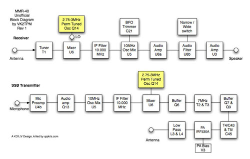
  Analyzing the MMR40 PTO – Manual Calculations Filed in Kits on Jan.25, 2009 The MMR40 Permeability Tuned Oscillator is the variable frequency control for the rig. It is used as one of the frequency sources for the first mixer(closest to the antenna), with the other source being the receive signal in receive, or the 10Mhz IF signal in transmit. MMR40 PTO Block Diagram The PTO consists of the following components: Q14 Oscillator Transistor D1 rectifier for AGC negative bias to Q14 gate R2 Load Bias Resistor C1 Coupling/Blocking Capacitor C4 and C8 Frequency Determining Capacitors S2 Band Segment Switch L1 Frequency Determining Permeability Tuned Inductor L2 Frequency Determining Fixed Toroid Inductor C9 Bypass Capacitor R1 Current Limiting Resistor MMR40 PTO Schematic Q14 is a J310 fet configured as a Hartley Oscillator. The oscillator is tuned by a brass screw through the middle of Inductor L1. In order to limit the number of turns on L1, the torrid L2 is wound with addi

MMR-40 Active Audio Filter U8b

Image
  MMR-40 Active Audio Filter U8b Filed in Kits on Jan.16, 2009 U8b of the MMR40 provides a band pass audio filter, which has a peak at around 600 hz. U8b Block Diagram It consists of the following components: U8b Op Amp R42 Feedback Resistor C72, C73 Feedback Capacitors R40, R41 Input Resistors U8b Narrow Bandpass filter In this circuit, S1 bypasses u8b for wide response, or includes u8b for narrow. R42 and C73 form a high pass filter, while C72 and R40,R41 form a low pass filter. These two filters combine to create the bandpass filter. From http://www.ecircuitcenter.com/Circuits/MFB_bandpass/MFB_bandpass.htm , we can see some formulas to help evaluate this circuit. Bandpass RC Formulas Rin = (R40*R41)/(R40+R41) = (47k*1.5k)/(47k+1.5k) = 70.5k/48.5k = 1.45k So, in this case, our center frequency: Co = 1/(2*PI*C*(sqrt(100000*1450))) C0 = 1/(2*PI*C*12041.6) C0 = 1/(0.000000138*12041.6) = 600.77 hz Q = 0.5 *(sqrt(R42 /Rin)) Q = 0.5 *(sqrt(100000/1450) Q = 0.5 * 8.30 Q

MMR-40 Active Audio Filters – U8a

Image
MMR-40 Active Audio Filters – U8a Filed in Kits on Jan.16, 2009 The next step was the Active Audio Filters. U8a - Audio Amp U8b - Filter Amp C42 - Coupling Capacitor C47 and R16 - Low Pass Filter R14, R40, R41, R42 C72, C73 Block Diagram from http://www.web.mac.com/petermarxy/MMR-40BlockDiagram (no longer active) U8a First Audio Amplifier There is some rolloff at the high end from R16 and C47 and U8a. This forms a low pass filter. It is bounded by the Equation: Where Fc = Cutoff Frequency, Rf = Feedback Resistance, Cf = Feedback Capacitance Cf = 1/2(PI)(fc)(Rf) and fc = 1/(2(PI)(Cf)(Rf)) or Cutoff Frequency = 1/(2(PI)(Cf)(Rf)) Cutoff Frequency = 1/2(PI)(0.00033) Cutoff Frequency = 1/0.0020734 Cutoff Frequency = 482 hz That seems kind of a strange place to roll off the audio to me, so I did some investigation to see if I was getting this right Looking on the web, I find a Texas Instruments Application Report (SLA058 - Nov 2000) that confirms the formula I was using. L

MMR-40 U3 Audio Stage

Image
  MMR-40 U3 Audio Stage Filed in Kits on Jan.16, 2009 It was difficult to get a good read on the frequency response of the final audio stage, using the wav files sweeping through the audio portion. I could see that it was fairly flat, but I haven't figured out how to make the Spectran program take a sweep and keep the results on the display. So I dug out the noise generator that I had built on a breadboard earlier, and started doing some testing. First I wanted to see the audio spectrum of the noise generator by itself, as picked off from a 0.01uf capacitor. Breadboard Noise Source with 47uf coupling caps There was a high pass filter affect, with frequencies below about 300 hz rolled off. So I replaced the coupling capacitors in the last two stages with 47uf electrolytic capacitors. The resulting audio spectrum was much flatter, very usable in my opinion Baseline Audio Spectrum from Noise Source If you would draw a line right through the middle of the noise, it wo

Building the MMR-40 Final Audio Amplifier U3

Image
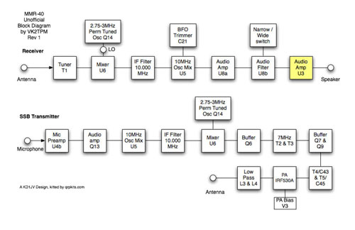
  Building the MMR-40 Final Audio Amplifier U3 Filed in Kits on Jan.11, 2009 I had decided to build this transceiver step by step, rather than just stuffing all of the components on the board, as the instructions stated. The next step for me was to build the audio circuits, starting with U3: U3 - LM386 Audio Amplifier V2 - Volume Control C54, C55, C56 – Bypass Capacitors C41 - Filter Capacitor C46, C50 - Coupling Capacitors R17 - load resistor Final Audio Amplifier The LM-386 is configured as is typical for these types of rigs. U3 Connections I was able to input an audio signal into the top of the volume control, and check the amplifier operation. I used a program on my PC to generate a sound file that was then played through my soundcard, using media player. The program is freeware found at heliso.tripod.com . I used a 20 – 3000 hz sweep signal here, but also made a two-tone signal for later testing. The output was read with my audio tracer, which has a level meter.

Building the MMR-40 40-meter SSB/CW Rig

Image
  Building the MMR-40 40-meter SSB/CW Rig Filed in Kits on Jan.11, 2009 The MMR-40 is a transceiver designed by KD1JV for the ARRL Homebrew Radio Challenge. It won the Non-Computerized category of the contest. It features both CW and SSB operation, with VFO frequency control and 5 watts output. I ordered one of the original kits from QRPKits.com when they first became available. I now see that they have an enhanced version of the kit available that has a steel case and Digital Dial included. The first step of assembly for me was to install the nuts that hold the brass screw which serves as the tuning rod in the Permeability Tuned Oscillator. This radio is a little unique, in that it uses a brass screw and hand-wound coil to control the frequency. Brass Tuning Mechanism It is important to make sure you leave enough space between the back two nuts that the nylon coil form has a little play in it. Once the screw and nuts were in place, I soldered the nuts to the board.