Posts

Showing posts from January, 2010

MMR40 S-Meter / Power Meter Circuit

Image
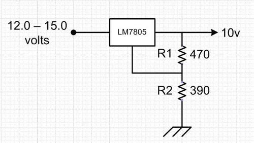
  MMR40 S-Meter / Power Meter Circuit Filed in homebrew on Jan.15, 2010 There is a simple S-meter/Power-meter circuit in the SPRAT Newsletter issue # 57 by Bill Bartlett, G4KIH. It derives its S-meter component from the audio stages, and gets its Power indication from a simple RF probe. To adapt this circuit to the MMR-40 took a little engineering, but it wasn’t too bad. MMR-40 S/RF Meter The original circuit is in Black above, with my modifications in Green. The modifications allow the use of a voltage regulator chip, rather than a 10 volt zener, which I didn’t have handy.  They also fix a problem with the power indication, described below. The first step was to figure out where to connect the circuit to the MMR-40.  The MMR-40 kit has a trace available off of U8 pin 1, labeled Audio Line Out on the board.  This is a good spot to pick up the audio for the S-meter, as it is before the volume control, so will not be affected by the setting of the volume.  There is one pro

More Volts from the LM7805 Regulator

Image
  More Volts from the LM7805 Regulator Filed in homebrew on Jan.10, 2010 I began development of an S-meter/Power meter interface for the MMR40 today. The plan calls for a 10 volt supply, using a 10 volt zener diode for regulation.  Since I didn’t have a 10-volt zener on hand, I decided to use an LM7805 regulator chip, but expand the voltage output to 10 volts from its normal 5 volts. To do that I used the method set out in an article by Sam Ulbing, N4UAU in the January, 1999 QST, page 45. The basic circuit looks like this: S-meter Voltage Regulator In the article, Sam gives the general guidance of setting the current through R1 at about 3 times the normal quiescent current for the 7805 regulator.  He goes on to give the formula for the Output voltage from the circuit: Vout = 5 volts + (5v/R1 + Iq)*R2 Vout = 5 + (5/470 + .003)*390 Vout = 5 + (0.0106 + 0.003)*390 Vout = 5 + (0.0136)*390 Vout = 5 + 5.304 Vout = 10.304 volts The device he was using had a quiescent rating o

Another MMR40 fix

Image
  Another MMR40 fix Filed in Kits on Jan.04, 2010 When I initially constructed the MMR40, I was going to use the original case.  So I put the band range switch on the bottom of the board to accommodate that.  Well with switching to the new case, I decided that I needed to move the switch to the front panel.  This had an unfortunate side effect.  It seems that the stray capacitance from the few inches of wire used to connect the new switch is enough to shift the VFO frequency down about17 kc.   Original Band Switch I had spent a good amount of time adjusting the coils of the VFO to make it cover from 7025 to about 7150 kc on CW, which includes the most popular QRP frequencies of 7040 and 7030 kc.  With the 17 khz offset, the new range was shifted to 7042 to 7170 kc. To rectify this problem, I pulled 1 turn off of the L2 toroid of the VFO circuit. L2 Toroid This shifted the VFO frequency up, and caused the rig’s final frequency to shift down.  So I now cover 7010 to 7

Some MMR40 Fixes

Image
  Some MMR40 Fixes Filed in Kits on Jan.04, 2010 While I was working on assembling the MMR40 into its chassis, I ran across a couple of problems. After I hooked up the antenna connector jumper from the SO-239 on the back of the chassis to the BNC connector on the board, I did a quick check of power out.  What’s this??? No Power?? How can that be??? Q9/Q10 circuit So I started thinking about what had changed… Mechanical assembly – no chance for metal to metal contact Added several header pins for connecting Counter, RF Probe, etc – check for shorts Removed band range switch and added header pins for outboard switch – check connections Added power switch and wiring – check connections Added Digital Dial Counter – check header connections – check BFO setting After checking all of this, I still had no power out.  So next, I dug out the scope and meter. The DC voltages to the TX/RX switching sections were as specified in the manual. The DC voltages on Q10 and Q9 were normal. Q9 w