Posts

Showing posts from May, 2012

8640Jr – Band 1 Lowpass Filter

Image
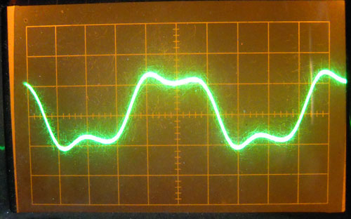
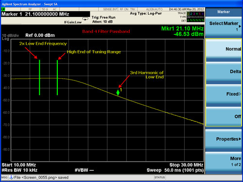
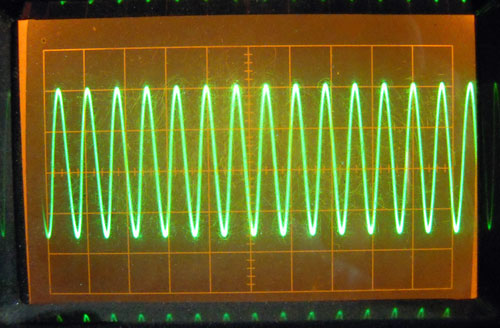
  8640Jr – Band 1 Lowpass Filter Filed in homebrew on May.20, 2012 The final band I added to the 8640Jr Signal Generator was for 850 – 1900 khz. I wanted to be able to cover 160 meters, and this allows the generator to do that, with Band 2 covering the top part of 160 meters, as well.   Band 1 Measured Response - New Filter As I built both additional bands at the same time, I made the same mistake on both. I miscalculated, and designed the filters to cutoff just after the third harmonic of the lowest frequencies, rather than the second, which would have placed it near the high end of the tuning range. The results were disappointing…   Band 1 Low Pass Filter Output - (original Bad) The high end of the band looked better, as it had for Band 2…   Band 1 Lowpass Filter Output - High End Original Filter The original design had the cutoff frequency way out at the edge of the third harmonic frequency of the low end of the range. As a result the third harmonic was only being attenu

8640Jr Band 2 Lowpass Filter

Image
  8640Jr Band 2 Lowpass Filter Filed in homebrew on May.19, 2012 After the first two filters of the original 8640Jr design had been built, I headed off in my own direction to add another two filters for lower bands. I miscalculated, and designed the filters to cutoff just after the third harmonic of the lowest frequencies, rather than the second, which would have placed it near the high end of the tuning range. The results were a little dismal at first…   Band 2 Lowpass Filter - Low End Bad Yeah, that is one ugly waveform. The high end of the band looked better…   Band 2 Low Pass Filter Output - High End Original design I didn’t catch this until I had already built the Band 1 filter with the same mistake. Oh well, that’s what makes it fun. So the original design had the cutoff frequency way out at the edge of the third harmonic frequency of the low end of the range. As a result the third harmonic was only being attenuated by a few db.   Original Band 2 Frequency response (B

8640Jr – Band 3 Lowpass Filter

Image
  8640Jr – Band 3 Lowpass Filter Filed in homebrew on May.19, 2012 There is a little distortion on the waveform of the Band 3 Low Pass Filter Output. The Spectrum Analyzer shows only about 14 db of attenuation on the 3rd harmonic of frequencies near the low end of the Range. This agrees with the predicted results below.     Band 3 Lowpass Filter Passband The original design looks like this…     Band 3 Lowpass Schematic The actual spectrum output looks like this on the low end of the range…     Band 3 Low Pass Filter Output Spectrum Things look better on the high end of the range, and the waveform looks better there, as well.     Band 3 Lowpass Filter Output Spectrum - High End of Range The predicted bandpass is as follows (10.5 mhz down about 15 db):     Band 3 Low Pass Filter Predicted passband Here are the waveforms… For the Low End Frequencies:     Band 3 Low Pass Filter Output - Low End of Range and for the High End…     Band 3 Low Pass Filter Output - High End of Range

8640Jr – Band 4 Low Pass Filter

Image
  8640Jr – Band 4 Low Pass Filter Filed in homebrew on May.19, 2012 There is a little distortion on the waveform of the Band 4 Low Pass Filter Output. The Spectrum Analyzer shows only about 14 db of attenuation on the 3rd harmonic of frequencies near the low end of the Range. This agrees with the predicted results below.     Band 4 Filter Passband The original design looks like this…     W7ZOI Band 4 Lowpass Filter Schematic The actual spectrum output looks like this on the low end of the range…   Spectrum Analysis of Band 4 Filter Output - Low end of Range Things look better on the high end of the range, and the waveform looks better there, as well.   Band 4 Low Pass Filter Output - High End of Range The predicted bandpass is as follows (21 mhz down about 12 db):     Band 4 predicted bandpass Here are the waveforms… For the Low End Frequencies:     Band 4 Waveform - Low end of Range and for the High End…     Band 4 waveform - High end of Range  

8640Jr – Band 5 VFO Output Measurements

Image
  8640Jr – Band 5 VFO Output Measurements Filed in homebrew on May.19, 2012 Band 5 on the 8640 Jr covers approximately 13.6 – 31 Mhz. There are now low pass filters configured for this band, but the output of the VFO has similar performance as the low pass filtered output of the other bands. Here is a photo of it’s waveform at the low end of its range.   Band 5 Waveform - Low End of Range And another of the upper end of its range…   Band 5 output - Upper end of range The spectrum shows the harmonics down about 30 db on the low end…   Band 5 spectrum - Low End of Range And on the high end of the range, the harmonics are down about 30 db, as well…   Band 5 Spectrum - High End of Range So it looks like if we shoot for around 30 db attenuation of the 3rd harmonic, we should have a pretty good waveform.      

8640Jr – Building the Low Pass Filters

Image
  8640Jr – Building the Low Pass Filters Filed in homebrew on May.19, 2012 I selected a small enclosure for the low pass filters. It was a little challenging getting all 4 filters into the small box, but it turned out pretty good. I started running out of room on the circuit board, so I started mounting the resistors standing up for the last couple. This photo was taken before I installed the final coupling cap from the switch to the output connector.   Low Pass Filter Assembly I used a pencil to help hold the toroid while I wound the coils. I got the idea from an article that I saw that said to use chopsticks. I didn’t have any chopsticks, but the pencil worked fine, and was much easier than trying to hold the toroid in my fingers.   Pencil toroid tool First (Band 4) Filter built…   Band 4 Filter Here is a close-up of the Band 4 filter. Note that I used 4 capacitors in the center PI leg, as I didn’t have 200pf capacitors, so had to use parallel 100 pf capacitors for each

8640Jr Bands

Image
  8640Jr Bands Filed in homebrew on May.19, 2012 My 8640Jr has 5 total bands, covering 850 Khz – 31 Mhz. I took some measurements with the Bandspread Control in the Maximum, Minimum and Midpoint of its range. I started with the VFO output frequencies, as all of the other bands are arrived at by dividing these frequencies down. With the Bandspread Capacitor set to Maximum, I had a range of 13.6 Mhz to 27.858 Mhz. Lowest Frequency with Bandspread Cap at Max     Highest Frequency with Bandspread Cap at Max   Next, I set the Bandspread Capacitor at Minimum. It is clear that this affects the high end of the range much more than the low end.   Lowest Frequency with Bandspread Cap at Min     Highest Frequency with Bandspread Cap at Minimum Finally, I set the Bandspread cap to the approximate center of its range, and made more measurements.   Lowest Frequency with Bandspread Cap at Mid     Highest Frequency with Bandspread Cap at Mid   Band 1     850.0000 Khz         1.9604  Mhz Band 2

8640Jr Divider Chain

Image
  8640Jr Divider Chain Filed in homebrew on May.05, 2012 The VFO of the 8640Jr runs from about 13.5 Mhz to about 31 Mhz. This frequency is run through a couple of dividers to yield a couple more bands. The divide by 2 band runs from about 6.75 Mhz to about 15.5 Mhz. This output is then divided again to yield a band from about 3.375 Mhz to about 7.75 Mhz. That is where the original design left off. I wanted to be able to at least cover the 160 meter band, so I added another chip and did two more divisions. So I have an additional band at 1.6875 Mhz to about 3.875 Mhz, and a final band at 834 khz to 1.9375 Mhz. Here is what the divider board looks like…   8640Jr Divider Chain The circuit was built on an old Radio Shack prototyping board that I had in my junkbox. The back side has some traces to ease the development process. That unsoldered connection in the upper right of the photo came back and bit me later, after I had soldered the board into the die-cast box. So I had