Heathkit TC-1 Tube Checker – Theory of Operation – Filament Check
Heathkit TC-1 Tube Checker – Theory of Operation – Filament Check
The TC-1 uses a neon bulb to sense relatively higher current flow in the plate circuit of the tube under test. It uses this function in order to detect short circuits between the various elements of the tube.
It uses this same circuitry to test whether a filament has continuity or is open. To set up the test, the tube tester is set to connect the plate and grids of the tube under test together and connect them to a 100vac source. The cathode and one side of the active filament are connected to the low side of the source transformer (o volt of the filament winding). The other side of the filament under test is connected to the appropriate filament voltage winding (i.e. 6.3 volts). This is the “normal” starting settings for testing the tube. The neon lamp does not light, because the current through the vacuum of the tube is not high enough to cause it to light.
When one is ready to test the filament, the filament voltage switch is set to its lowest setting (0.75v), in order to provide a low impedance return path for the test. Then the normally low side of the filament is switched in parallel with the plate circuit. This connects the 100 volt winding to the filament (through a very high value resistor – 270K ohm across the neon bulb, which limits the current to prevent burning out the filament). The low impedance of the filament causes a much higher current to flow through the resistor, creating a much higher voltage across the resistor. This higher voltage is high enough to cause the neon bulb to light, indicating that there is current flow through the filament, so it is presumably good.
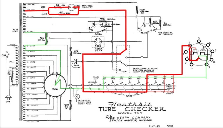
In the diagram below, you can see that the normal path for this circuit is in the faded red color. When the filament is added to the circuit, the bold red path indicates the higher current flow portion.
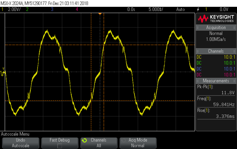
Under the normal setup, the neon bulb circuit has about 75 uA peak of current flowing through it, developing about 12 volts peak-peak across the network – not enough to fire the neon lamp.
When the “D” switch is moved to the top position for the filament check for this 12AU7 tube, it places one side of the filament in parallel with the grid and plate circuit. This causes the current through the neon bulb circuit to increase to about 1.5 ma peak, which develops about 263 volts peak-peak across the circuit. This is high enough to trigger the neon bulb, and it lights brightly, indicating that the filament is intact.


Comments
Post a Comment