Heathkit TC-1 Tube Checker – Theory of Operation – Line Set Mode
Heathkit TC-1 Tube Checker – Theory of Operation – Line Set Mode
Theory of Operation: Line Set Mode
In Line Set Mode, the TC-1 is set up to measure the 115 volt winding of the transformer, and set it to 115 volts, regardless of a variation in the line input voltage. This allows the checker to give valid go/no-go checks of tube emissions even if the line voltage is above or below the nominal 115 volt line voltage.
To make this reading, the circuit is set to read the voltage from the 115 volt winding, through the 75K ohm resistor TC49, the 1200 ohm resistor 012 (in parallel with the meter and diode string), and a portion of the Plate control TC11.
Because the 75K ohm resistor is so much larger than the other resistances, it pretty much sets the current through the circuit at about 1.5ma.
The Plate control varies between 0 and 200 ohms, but does not really affect the reading because the 75K ohm resistor dominates the circuit, and adjusting the plate control changes the voltage on both sides of the 1200 ohm resistor equally, so the meter still reads accurately across the 1200 ohm resistor.
The meter is a 1ma full scale movement. Because we want the meter to be centered for this reading, that means that 0.5ma will be flowing through the meter and diode combination. And that leaves 1ma to flow through the 1200 ohm resistor.
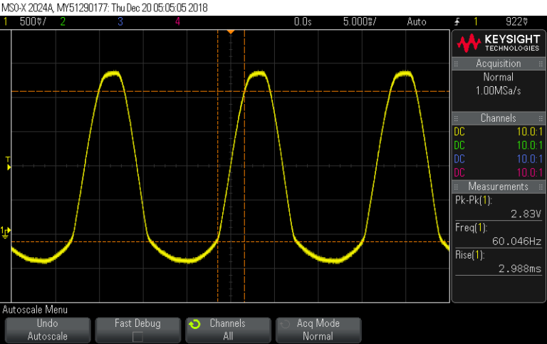
Measuring across the 1200 ohm resistor, our scope shows a 2.83 Vpp drop. Converting this to rms values shows:
- (Vpp /2) * 0.707 = Vrms
- (2.83 / 2) * 0.707 = ~ 1.000 Vrms
Measuring across the diode, our scope shows a 2.63 Vpp drop. Converting this to rms values shows:
- (Vpp /2) * 0.707 = Vrms
- (2.63 / 2) * 0.707 = ~ 0.93 Vrms
And using this voltage drop, and knowing it is passing 0.5 ma of current, we can find the forward resistance of the diode:
- R = E / I
- R = 0.93 / 0.0005
- R = ~ 1860 ohms
Next, we can read the voltage drop across the meter, to determine the meter resistance. Our scope shows about 250 mvpp across the terminals. **Note: Though the scope “measured” 422 mv, it was reading the tiny spikes above and below the main waveform. But we can see that the main waveform is about 2.5 divisions high, or 250 mvpp.
- Vrms = (Vpp / 2) * 0.707
- Vrms = (0.250 /2) * 0.707
- Vrms = 0.125 * 0.707
- Vrms = 0.088 volts
- R = E/I
- R = 0.088 / 0.0005
- R = ~ 176 ohms
So the total resistance of the meter/diode string is about 2036 ohms.
And the total resistance of the meter circuit in parallel with the 1200 ohm resistor is:
- Rt = (R1 x R2) / (R1 + R2)
- Rt = (2036 x 1200) / (2036 + 1200)
- Rt = 2443200 / 3236
- Rt = ~755 ohms
So to sum it up, when 115 volts is coming out of the transformer, it causes 1.5ma of current flow through the 75K resistor. This 1.5ma splits into 0.5 ma through the meter/diode leg and 1.0ma through the 1200 ohm resistor, developing about 1 volt across the resistor. This causes the meter to swing to half scale, representing the normal line voltage. If the reading is off one way or the other, the operator raises or lowers the voltage on the primary of the transformer by turning the “Line Set” control until the meter reads half scale.
On my TC-1, I found that I could adjust for any line voltage between 107 and 130 volts input.


Comments
Post a Comment