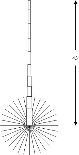
43′ Vertical – Part 5 – Matching Network

43′ Vertical – Part 5 – Matching Network Filed in Antennas on Jun.20, 2010 Next on the list for the 43′ vertical project was the base matching network, to allow reasonable matching to the rig on all bands from 160 meters through 6 meters… I started by mounting the 4:1 Unun from MFJ on a fiberglass plate, to give it good high voltage characteristics. This Unun is at a very high impedance point on 160 meters, so develops some very high voltages (up to 5000 volts or more, depending on power levels). The Unun was attached with a 1/4″ x 20 screw through both boards, forming a sandwich. It is used to drop the high impedance down to a more manageable level on the ham bands. It basically divides the impedance at the antenna by 4. Because the coil needs to be about 46 uh, it is too long to fit all in one piece. So it is cut in two sections and mounted seperately. By putting the two sections in series, the inductances still add up....