Tektronix 2465A Oscilloscope Repair – Part 4
Tektronix 2465A Oscilloscope Repair – Part 4
CRT Screen Adjustments
After the initial Low Voltage Power Supply adjustments, the next step is to run through the CRT screen adjustments. I was thrown off here at first by the order that the adjustments show up in the manual.
The manual starts off the Adjustments section with an Introduction, followed by a Power Supply procedure. It then continues with CRT Adjustments, but for the 2467 scope with serial numbers B011012 and up. This is not the section I needed, as my scope is a 2465A with a low serial number. Here is the order of the manual, with the sections for my scope highlighted and numbered in the order I used. Lesson – Pay attention to your particular model number and serial number…
Power Supplies (01)
2467 CRT Adjustments – Serial Number B011012 and Up
2465A CRT Adjustments – Serial Number B014331 and Up
CAL 01 – Horizontal (03)
CAL 02 – Vertical (04)
CAL 03 – Triggering (05)
CAL 04 – CH 2 Delay Enable/Disable (06)
CAL 05 – Set HRS ON and PWR ON/OFF Cycles (07)
CAL 06 – Vertical Transient Response (08)
CAL 07 – Readout Centering and Gain (09)
Dynamic Centering, DC Balance, and X-Y Phase Differential Adjustments (10)
2467 CRT Adjustments – Serial Number B011011 and Before
2465A CRT Adjustments – Serial Number B014330 and Before (02)
Step 1:
The first step of this section is to adjust the Astig Preset and Grid Bias. First we position the spot in the middle of the screen. Then we adjust the Focus control and the Astig control on the front panel for the sharpest dot possible.

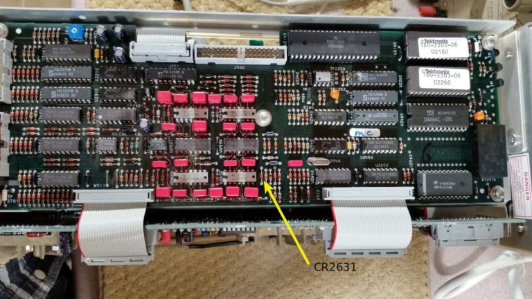
Next, we find a test point on the control board (CR2631 Cathode), and set up a voltmeter reading on it. We use the intensity control to set this test point at 1.00 volts.

With this voltage set, we now adjust the Grid Bias potentiometer for a barely visible dot. Finally, we check to make sure that no dot is visible with the intensity turned all the way down.
Step 2:
In Step 2, we are adjusting the horizontal and vertical traces to align with the screen graticule.
Here are the adjustment points:


and here is the result:

Step 3:
In step 3, we are adjusting the display to have a minimum of curvature from one end to the other.
We feed in 1us time marks from our function generator, and configure the scope to overscan on the display. Then we adjust the Geometry potentiometer for the straightest display, with as little curvature as possible.


Step 4:
Step 4 is adjusting the edge focus. We set it up with an 8-division sine wave at 50 Khz. Then we adjust the Edge Focus potentiometer and the front panel Focus and Astig controls for the best overall focus.


Result:

Step 5:
In step 5, we apply a 10 Mhz, 6 division signal to the scope. We adjust the High Drive Focus control for best focus.


That’s all for the CRT Adjustments. Stay tuned for more off-the-cuff calibrations…


Comments
Post a Comment