Tektronix 2465A Oscilloscope Repair – Part 9
Tektronix 2465A Oscilloscope Repair – Part 9
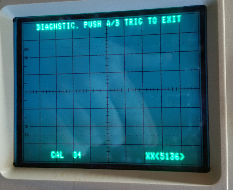
CAL04 – Ch 2 Delay Enable/Disable
For this section, I am simply enabling the Channel 2 Delay function and checking functionality with it enabled. I could choose to leave it enabled, or to disable it. I left mine enabled.
Steps a – d start up the procedure and allowed me to flip back and forth between CH 2 Delay Enabled and Disabled. After selecting “Enabled” I pressed the A/B Trig button to leave the function.
In steps e – f, I set up a narrow pulse at 100 Khz. Since I do not have a Calibration Generator, I used the pulse output from my Agilent scope’s function generator. It’s not a terribly fast rise time, but seems to work for this check. The procedure calls for using a dual-input coupler, which I do not have. I simply used a BNC T to feed both channels with identical length RG-58 cables.
In step g – i, I set the generator to create a 5 division pulse on the screen, then overlapped the two channel traces near the center of the screen using the Channel 1 & 2 position controls. I set the rising edge to the center of the screen with the horizontal position control. Then I enabled the x10 magnification.
Steps j – m had me pull out the SEC/DIV knob to turn on the channel 2 delay function. Then I used the delta control to move channel 2 forward and back from channel 1, finally returning it to overlap. It’s hard to see the separation, because my pulse does not rise fast enough, but I was able to see the two traces separate slightly. The photo was taken before I separated the traces.
Since I wanted to leave this function enabled, I stopped at this point, rather than returning to the CAL04 menu to disable it.


Comments
Post a Comment