Tektronix 2465A Oscilloscope Repair - Part 12
Tektronix 2465A Oscilloscope Repair - Part 12
CAL07 – Readout Centering and Gain
We are near the end of the poor man’s calibration of the 2465A Oscilloscope.
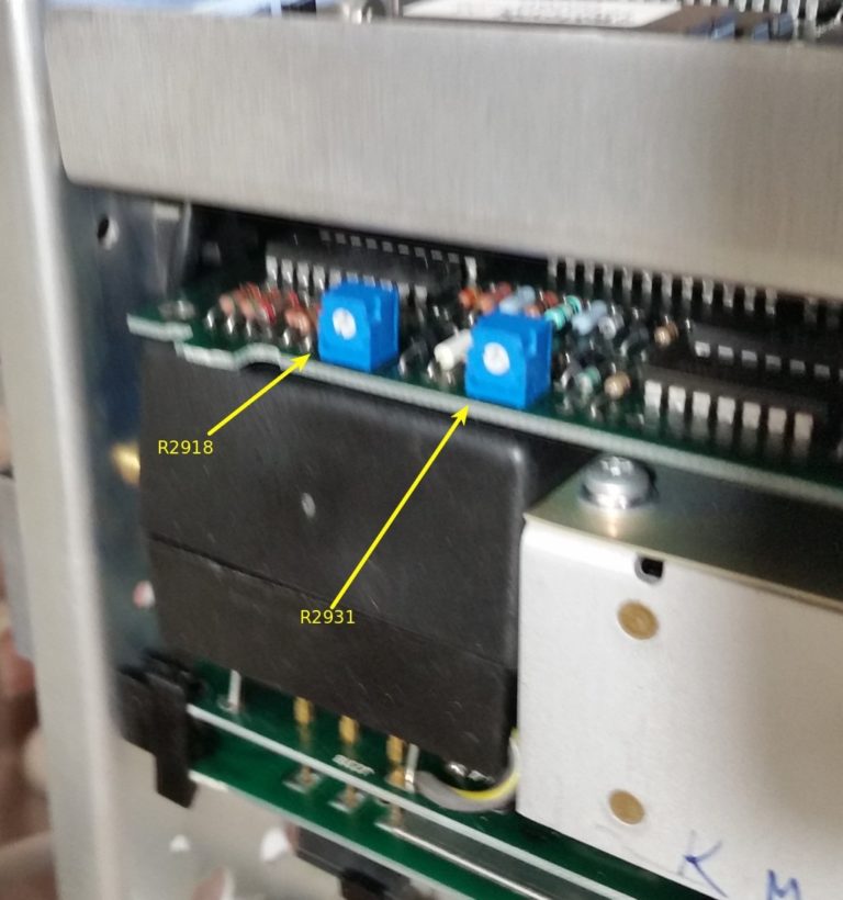
CAL07 adjust the position of the Readout characters on the screen. They are simply moved with two controls (R2918 and R2931) to place them just inside of the graticle area of the screen.

The adjustments are on the small card accessed from the top of the scope opposite the CRT.

Once the display is centered, it is time to move the CAL Jumper back to the “NO CAL” position.
The second half of this procedure seems to be adjusting the Limited Bandwidth parameters with the 20 Mhz Bandwidth Limit turned ON.
The adjustment is coil L644.


I simply applied a 100 Khz, 5 division square wave and adjusted for the flattest waveform. No problems here. I did not get a picture of the waveform.


Comments
Post a Comment