Tektronix 2465A Oscilloscope Repair - Part 11
Tektronix 2465A Oscilloscope Repair - Part 11
CAL 06 – Vertical Transient Response
Now comes the most difficult part of the calibration – The Vertical Transient Response.
The goal of this procedure is to end up with a scope that is relatively flat across its bandwidth. It uses a very fast rise time pulse to make the adjustment, and I just do not have one available. When I first checked the bandwidth, it fell off drastically at 8 Mhz, and was nearly unusable at 350 Mhz. There were several significant dips and peaks as I swept the input sine wave from 1 Mhz to 350 Mhz, and I hoped that these would be corrected when I finished.
Steps a – c start up the procedure.

Steps d – f cover setting up the pulse to channel 1. I used the fastest rise time pulse I could find in my shop, and still had a 40ns rise time – way too long to be very effective. I did have a 10db attenuator that I threw in line, but it made no difference in my results.
Step g contains instructions for presetting the controls that will be adjusted.


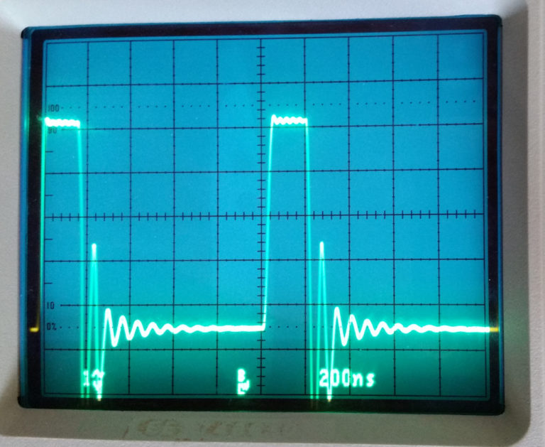
Steps h – p are the adjustments to make. As I said, I was not able to see many changes in the waveform for the adjustments with the setup I had the first go-around. For my second pass through, I experimented with putting a resistor in series with the coax cable, and tee-ing off the signal to a second scope with another coax. After trying several resistors, I found that putting a 10-K ohm resistor in line with that setup resulted in a waveform with several pulses off the ringing leading edge. These had quite a bit faster rise time, and I was able to see some progress by using the fastest of these pulses. This eventually resulted in a much better, but not perfect bandpass. Unfortunately, I did not get a photo of the better pulse.
Steps q – r are connecting the sine wave generator to the scope at a low frequency (I chose 1 Mhz), and setting it for 6 divisions in height.
Steps s – v check the level of the sine wave at 250 – 350 Mhz, and adjusting the HF adjust control to meet the specification.
Steps w – ll seem to be running through different voltage input settings, and adjusting the delta control for the best waveform in each step. I don’t have the several different attenuators, so I just adjusted the function generator output to 5 divisions for each setting, then attempted the adjustment noted in the steps. It didn’t seem to make a lot of difference, so I’m sure this is not adjusted as well as it could be. But I think it will be OK for my hobby, amateur use.
Steps mm – oo adjust the vertical center and gain. There were no problems with these steps.

The final result?

Well, I fell short of the 350 Mhz bandwidth. I’ll have to build or purchase a more appropriate avalanche pulse circuit to try this again in the future. It is still very usable, with the 3db bandwidth being about 150 Mhz.


Comments
Post a Comment