Tektronix 2465A Oscilloscope Repair – Part 7
Tektronix 2465A Oscilloscope Repair – Part 7
CAL 02 – Vertical Adjustments
The purpose of this adjustment it to set the calibration parameters for the vertical gain of the scope at the various input voltage ranges.
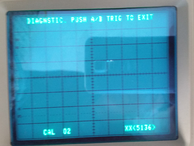
On starting the CAL02 procedure, it automatically runs through some internal tests, incrementing the step counter from 100 – 110, stopping at step 111.
At this point, you are prompted to input various “Standard Amplitude Signals” into the Channel 1 or Channel 2 input BNC connectors. From my research, it appears that “Standard Amplitude” means a square wave at 50% duty cycle, at 1Khz frequency. The amplitude is set at the generator to match the requirements in the instructions.
In steps CAL02 e – g, you are inputting a 500mv, 1Khz square wave to channel 1 and using the Channel 2 position to move the two displayed dots up and down to align them with the center graticle. Then you use the Channel 1 position control and Channel 1 Volts/Div Var control to move the two dots right and left so they line up with the first and last lines of the graticle on the edges of the screen.
When you press the Upper Trigger Coupling switch to advance, both steps 111 and 112 are run.
For CAL02 h – j, you are inputting a square wave signal of the voltage indicated in the table 5-4, and setting the Channel 1 volts/Div switch to the corresponding voltage for each step (113 – 120).
Note that step 120 calls for a 10 volt standard amplitude signal. This was beyond the range of my function generator, so I had to find an older function generator that I had laying around that would generate that high of a voltage signal. It does not have a calibrated output, so I fed the output to a second scope that I have to adjust it to precisely 10 vpp. The same needs to be done for step 130 (Channel 2, below).
From this point forward, there was not really anything to watch on the screen, so I have no photos.
Steps k – m appears to set up a beginning vertical calibration for channel 2.
Steps n – p mirror steps h – j (above) but for Channel 2.
After completing the Channel 2 adjustments, the scope will automatically run through the DC balance adjustments 130 – 141.
With steps r – s, you are calibrating the Delta-v (Voltage) cursors, using a 50 mv standard amplitude signal.
Steps t – w calibrate the Vertical Center and Gain of the scope.
And that concludes the CAL02 Vertical Calibration Section.


Comments
Post a Comment