Analyzing the MMR40 PTO – Manual Calculations
Analyzing the MMR40 PTO – Manual Calculations
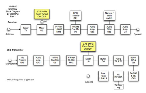
The MMR40 Permeability Tuned Oscillator is the variable frequency control for the rig.
It is used as one of the frequency sources for the first mixer(closest
to the antenna), with the other source being the receive signal in
receive, or the 10Mhz IF signal in transmit.
The PTO consists of the following components:
- Q14 Oscillator Transistor
- D1 rectifier for AGC negative bias to Q14 gate
- R2 Load Bias Resistor
- C1 Coupling/Blocking Capacitor
- C4 and C8 Frequency Determining Capacitors
- S2 Band Segment Switch
- L1 Frequency Determining Permeability Tuned Inductor
- L2 Frequency Determining Fixed Toroid Inductor
- C9 Bypass Capacitor
- R1 Current Limiting Resistor
Q14 is a J310 fet configured as a Hartley Oscillator. The oscillator is tuned by a brass screw through the middle of Inductor L1. In order to limit the number of turns on L1, the torrid L2 is wound with additional turns. The PTO has about 130khz of tuning range, given the capacitance of C8 to work with. By attaching capacitor C4 in parallel with C8, we are provided with a second range of approximately 130 kHz in the lower range of oscillation.
The inductive reactance of L1/L2 would ideally be about 100 ohms at the resonant frequency, according to EMRFD (Experimental Methods for Radio Frequency Design by Wes Hayward).
R2 acts as a load on the tank circuit, and a discharge path for blocking capacitor C1.
The Total tank capacitance is (C4 and C8 sometimes paralleled)
Calculating L2 Inductance:
39 turns on a T37-2 core
Diz's Website Toroid Windings Page gives us the formula and some tables to determine inductance from Core Type and number of turns.
The T37-2 core has an Al value of 40. The formula for inductance here is uh = (AL * Turns2) / 10000
uh = (40 * 28^2)/10000
uh = (40 * 784)/10000
uh = (31360)/10000
uh = 3.136
Calculating L1 Inductance:
From the Arrl Handbook, L1 inductance (without the brass screw) is
determined by the formula uh =(d^2 * n^2)/((18 * d)+(40 * l)), where:
d = diameter of coil in inches
l = coil length in inches
n = number of turns
L1 is wound on a #6 nylon spacer, which is hexagonal in shape. Using my micrometer, the diameter from flat side to flat side is 0.260 inches. From corner to corner, it is 0.285 inches. I’ll assume an average diameter of 0.2725 inches. The length of the coil is about 0.385 inches.
So, plugging in our values:
uh = ((0.2725^2)*(39^2))/((18 * 0.2725)+(40 * 0.385))
uh = (0.07425625 * 1521)/(4.905 + 15.4)
uh = 112.94/20.305
uh = 5.562
Inductances add in series, like Resistances, so we have a total of 8.698 uh
Calculating our Resonant Frequency:
So let's see if we are in the right ballpark
The Tank Resonant Frequency is given by 1/((2*PI)(sqrt(L*C)))
Substituting our values gives us:
F = 1/((6.28)*(sqrt(0.000008698 * .000000000330))
F = 1/((6.28 *(sqrt(0.0000000000000000287034))
F = 1/(6.28 * 0.000000053576)
F = 1/0.0000003366
F = 2.970663 Mhz
So this is very close to the design frequency range of 2.75 - 3.00 MHz.
The inductive reactance of the 8.698uh total inductance at 2.875mhz would be:
(2)(PI)(F)(L) = 2 * 6.28 * 2875000 * 0.000008698
= 157 ohms, very close to the 100 ohms recommended by EMRFD.
Migrated Comments:
One Response to “Analyzing the MMR40 PTO – Manual Calculations”


May 5th, 2011 at 2:11 am
oops, found them here sir Thanks a ton for this information!