MMR-40 U3 Audio Stage
MMR-40 U3 Audio Stage
It was difficult to get a good read on the frequency response of the final audio stage, using the wav files sweeping through the audio portion. I could see that it was fairly flat, but I haven't figured out how to make the Spectran program take a sweep and keep the results on the display.
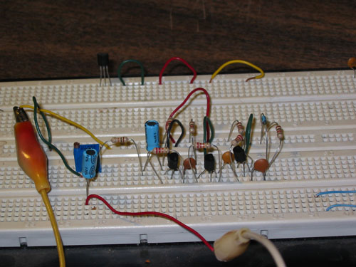
So I dug out the noise generator that I had built on a breadboard earlier, and started doing some testing. First I wanted to see the audio spectrum of the noise generator by itself, as picked off from a 0.01uf capacitor.
There was a high pass filter affect, with frequencies below about 300 hz rolled off. So I replaced the coupling capacitors in the last two stages with 47uf electrolytic capacitors. The resulting audio spectrum was much flatter, very usable in my opinion

If you would draw a line right through the middle of the noise, it would average about -75db on this display.
So next, I coupled the noise generator to the input of U3. While monitoring it with Spectran, it shows a little low pass filter type rolloff, I'm guessing from the coupling capacitor in the circuit, but I don't really know why.


But the output of U3 is nice and flat

And it continues that flat at least up to 5200 hz.
In CW transmit mode, the cw sidetone is fed into pin 3, the second input to U3. This provides a sidetone with its own separate volume control.


Comments
Post a Comment