Posts

Field Day 2010 Operations
Image
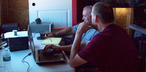
  Field Day 2010 Operations Filed in Contests on Jul.07, 2010 Conditions were generally not as good this year as last. We found that the settings for the antenna tuner that we made last year were still completely valid. The only problem we had was when we had the 160 meter switch turned on for 80 meters at one point, which may have led to some dismal results there. Ken (KF7FAM) joined John and I for his first Field Day this year. He started out by helping out with antenna construction, then by watching and logging while he learned the flow of the Field Day contact.   Ken logs as Randy operates     Later, he got more ambitious, and had his first HF contact, followed by several more throughout the weekend. I think he enjoyed each new section he contacted. As usual, we wern’t trying to maximize points, but were more interested in the technical setup, and the challenge of contacting as many sections as possible.   Ken making one of several HF contacts...

Field Day 2010 – Preparations Part 2

Image
  Field Day 2010 – Preparations Part 2 Filed in Contests on Jul.07, 2010 We first tried using the Receiver Noise Bridge to check the antenna operation, but could not get reasonable nulls an any band.  That was our first sign of trouble.  After hooking up the radio and the bias-T connections, we found the operation of the vertical pretty dismal on all bands.  We hauled out a battery to energize the band switching arrangement as needed while troubleshooting.   After fields day operations had started, we continued to debug the problem, while simultaneously doing some operating with the 135′ doublet (which worked great, as always!) We found some wiring errors, and fixed them.  Our expectations were high, but again, the antenna just did not perform well.   We decided to go back to basics and check with the simplest configuration.  We took the noise bridge out and measured the resonant frequency of the antenna with no matching network....

Field Day 2010 – Preparations

Image
  Field Day 2010 – Preparations Filed in Contests on Jul.07, 2010 For Field Day this year, we had 3 members to our group.  John (WB0WHO), Ken (KF7FAM) and Randy (WB0SMX).  We needed to finish up the installation of the 43′ vertical that we hoped would complement the operation of the 135′ doublet that we used last year. We brought along the 80/160 meter matching network and installed it at the base of the vertical.   Ken and John measured out about 36 radials, each 40′ long for the ground plane.     Next, we needed to terminate the 150′ of LMR-400DB Direct Burial coax.  This coax has a little better loss characteristics than the typical RG-8, and can be buried underground without a conduit.  It has the sticky waterproof gel inside that you sometimes see in direct burial telephone cable.  We used gasoline to clean it off of the ends (be careful!).   It was a challenge untangling all of the radials from one another.  We f...

43′ Vertical – Part 5 – Matching Network

Image
  43′ Vertical – Part 5 – Matching Network Filed in Antennas on Jun.20, 2010 Next on the list for the 43′ vertical project was the base matching network, to allow reasonable matching to the rig on all bands from 160 meters through 6 meters…   I started by mounting the 4:1 Unun from MFJ on a fiberglass plate, to give it good high voltage characteristics.  This Unun is at a very high impedance point on 160 meters, so develops some very high voltages (up to 5000 volts or more, depending on power levels). The Unun was attached with a 1/4″ x 20 screw through both boards, forming a sandwich.  It is used to drop the high impedance down to a more manageable level on the ham bands.  It basically divides the impedance at the antenna by 4.   Because the coil needs to be about 46 uh, it is too long to fit all in one piece.  So it is cut in two sections and mounted seperately.  By putting the two sections in series, the inductances still add up....

New Etching Solution

Image
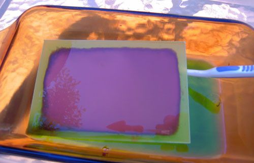
  New Etching Solution Filed in homebrew on Jun.20, 2010 When I started working on my matching network for the 43′ vertical, I needed some mounting plates made from fiberglass (high voltage resistant…)  I had read in the QRP-tech yahoo pages that you could use a combination of Hydrogen Peroxide and Muriatic Acid to do the etching.  I had use Ferric Chloride before, and found it to be messy, and somewhat of an environmental hazard.  You really don’t want to pour that stuff out just anywhere… So I mixed 1/2 cup of hydrogen peroxide with 1/4 cup of muriatic acid (like you use in your pool).  I put the copper plated fiberglass into the solution and gently scrubbed it with an old toothbrush.  It only took about 5 minutes for all of the copper to dissolve.   The result was a nice clean piece of fiberglass, and some easily neutralized (with baking soda) etching solution that was safe to dispose of.  Migrated Comments: 2 Responses to “New Et...

43′ Vertical – Part 4

Image
  43′ Vertical – Part 4 Filed in Antennas on Jun.20, 2010 When I arrived on Friday, I got out the post hole digger and dug a hole about 2 feet deep. The post was set into the hole and prepared for cement. The radial plate was attached to fix the height above ground level.   The post was leveled on Saturday, and cement was mixed and poured into the hole.  Only one 60 lb. bag was used, as this was a pretty small hole.   After the cement dried for several hours, the remaining few inches were filled with dirt from the hole.  This was done to facilitate moving the antenna to a different location at some point.  I could just cut off the post below ground level and not have to worry about removing the cement portion.   I wanted to be able to telescope the tubing sections up and down, so that the antenna could be easily lowered when we were not up at the ranch using it. But when I started sliding the tubing sections together, the second and third...

43′ Vertical – Part 3

Image
  43′ Vertical – Part 3 Filed in Antennas on Jun.20, 2010 The next step was to attach the aluminum tubes to the 4×4 pressure treated post for mounting in the field. I used some 2″ conduit brackets and some 2″ PVC parts to do that.   For the top of the mount, I used a piece of 2″ schedule 40 PVC pipe.  At first I tried to just compress the pipe around the tubing, but it would not compress enough.  So I used my coping saw to cut a slit in the tubing, to allow space for it to compress.  That seems to have worked nicely.   For the bottom, I use a 2″x1″ schedule 40 bushing, with a 1″ x 3/4″ threaded adapter. I thought I might be able to clamp this part as well, but due to its complex structure, it was not possible to compress it.  I will rely on the clamp and copper pipe into the ground to keep it in place, and let the antenna sit on top of it.  That should keep the bottom for hinging out in the wind.   At this stage, I headed up to th...