8640 Jr Attenuator
8640 Jr Attenuator
Now that we have pretty good output on all bands, I wanted to be able to attenuate the signal to be able to use it for receiver testing. This required approximately 100 db of switchable attenuation. As a young Avionics Tech in the Marine Corps, I used an old tube-type signal generator called the URM-25d. The attenuator in it was adjustable in 20 db steps, so each step cut the signal voltage level by a factor of 10. I like that arrangement, and fancied myself doing something similar here.

The URM-25d also had a fine attenuation control that let you dial the signal up or down between the x10 steps. So you could dial in precisely the signal level you wanted.
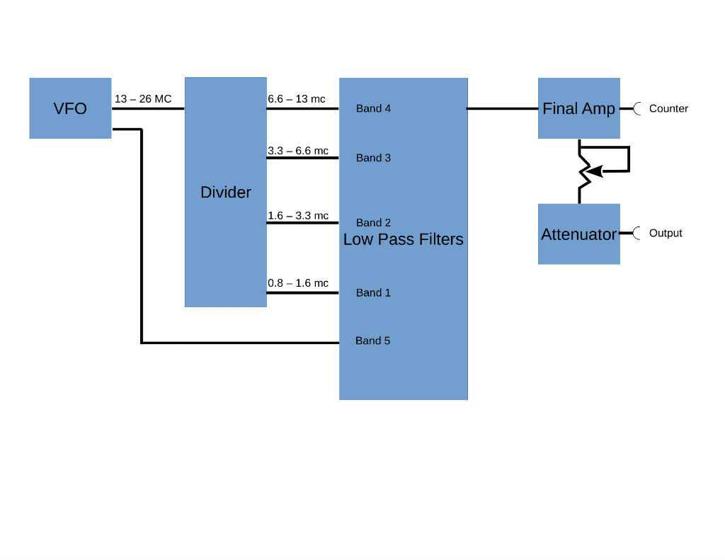
The way the attenuator worked was that there was a metering circuit at the high level that was fairly easy to meter. So you would set the meter to a “Set” mark on the meter, which represented 2 volts RMS. Once that was set, the precision attenuator would step down the actual output signal by a factor of 10 for each step, eventually getting to where you could get to levels lower than 1 uv.
Then there was also a fine attenuation setting, which allowed fine control in between the steps.
The fine control was basically a 500 ohm variable resistor in series with the high level output signal. This then fed the rotary step attenuator for the final output.
I found a nice rotary switch that looked like it would work, then found a combination of parallel resistors to get really close to 61.1 and 495 ohms. I built up the attenuator using these parts and installed it into the front of my signal generator faceplate. After hooking it up to my station receiver, it was kind of successful, but not good enough. I could only get down to about 50 uv as a lowest level. There was just too much bleed through in the rotary switch.
Feeling thoroughly frustrated, I tore it all out, and forgot to take any pictures!
For my second attempt, I built a shielded box with shields between each section of the attenuator. All made with double sided PC board. I can’t say much about my mechanical PC Board construction skills, other than it is ugly and works. I followed the plan from the QST September 1982 article by WA0UZO and N1FB, using slide switches and standard resistor values that are close enough for my purposes. I used only 20 db sections and made 5 of them for a total of 100 db attenuation (plus about 6 – 8b more from the variable fine control).

Finally, I attached a lid made of the same material.

OK, so it’s ugly… Really ugly. How does it work? Amazing. I can now dial down the level of the signal generator to a level that does not even move the S meter on the radio. I can’t completely eliminate it without disconnecting the cable, but it’s close enough.
Next is to make the faceplate to finish it off.


Comments
Post a Comment