Posts

Heathkit IG-42 Signal Generator Restoration – Part 4
Image
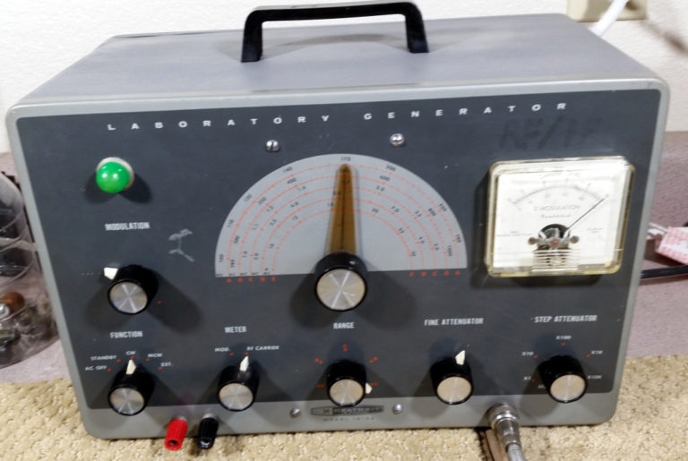
  Heathkit IG-42 Signal Generator Restoration – Part 4 Filed in Heathkit IG-42 on Oct.02, 2018 Cabinet Repair   Front Panel Now the the IG-42 was in good electrical order, it was time to move on to the cabinet repair. As you may recall the cabinet was in a pretty sorry state when I received it.   Cabinet Top – Start   Front Panel – Start I removed all hardware from the cabinet and washed it with soap and water.  Then I used a small ball pean hammer to knock out the dent in the corner to some extent (I’m no body man…)  This was followed by a light sanding with wet/dry sandpaper and water. I then applied a coat of primer to the cabinet and let it dry overnight.  The next day, I found that the primer did not stick very well to the existing paint.  I don’t know if it was the original rough finish, or some remaining grease, or just a mismatch in paint types. I sanded the area again lightly, as before and applied a second coat of primer....
Heathkit IG-42 Signal Generator Restoration – Part 3

Image
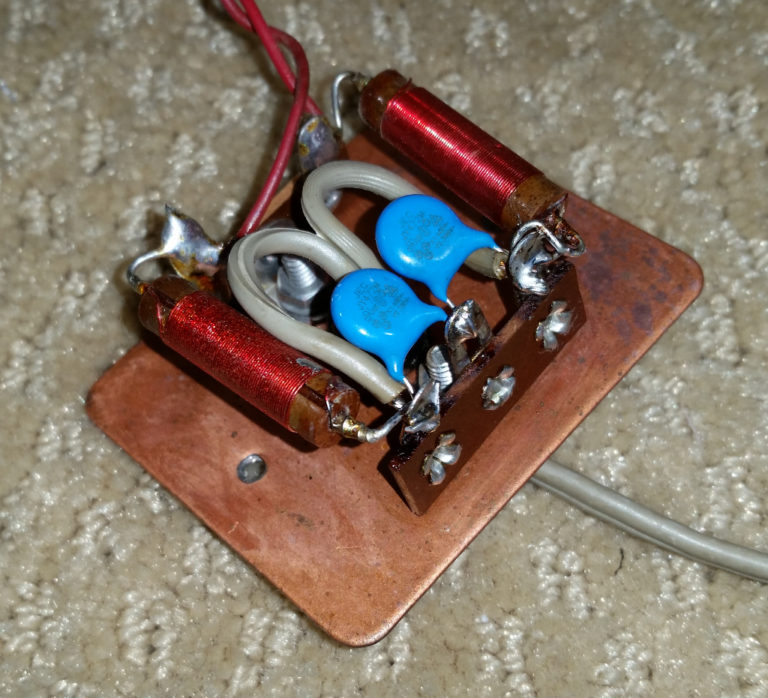
  Heathkit IG-42 Signal Generator Restoration – Part 3 Filed in Heathkit IG-42 on Oct.02, 2018 Line Cord and Chassis repair — To continue on with the restoration, I replaced the ceramic disk filter capacitors on the line cord input with safety capacitors.  These are designed to fail to an open state, rather than a shorted state.  We hope that they never fail, but if they do, it should leave the chassis safely isolated from the line voltage, regardless of which way the old style plug is plugged in to the wall.   Line Cord safety caps installed Next, I cleaned all tube sockets and switches and potentiometers with Caig DeOxit D5 cleaner.   Caig DeOxit D5 Then I applied DeOxit F5 Fader Lube to the potentiometers.   Caig Fader/Lube F5 I continued with a drop of 3-in-1 oil to the bearings of the variable capacitor.   3-In-1 Oil Once all of this was done, I became aware of the really poor condition of the chassis.  Despite my efforts, it was st...

Heathkit IG-42 Signal Generator Restoration – Part 2

Image
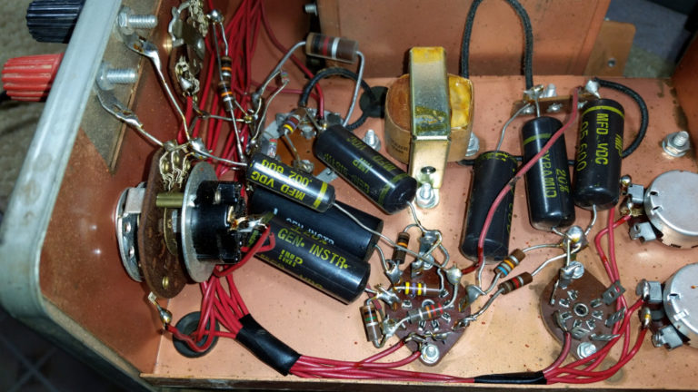
  Heathkit IG-42 Signal Generator Restoration – Part 2 Filed in Heathkit IG-42 on Apr.02, 2018 Electrolytic Can Capacitor Re-stuffing Next on the repair plan is to pull the 3-section electrolytic can capacitor, and re-stuff it with modern electrolytic capacitors.  This will ensure reliable operation for decades into the future, while preserving the looks of the old equipment.  I unsoldered the two resistors, the .05 uf capacitor and the various wires from the terminals of the can, being careful to note what each terminal had for connections.  Once that was done, I was able to unscrew the two screws holding the can to the chassis, and remove the can.     Electrolytic Can Capacitor removed from chassis The can bracket lifted off, after un-twisting the four tabs on the can. I worked for about a half hour, attempting to uncrimp the edge of the aluminum can from the bottom.  I tried a pocket knife and a small screwdriver, but I got nowhere in ...

Heathkit IG-42 Signal Generator Restoration – Part 1

Image
  Heathkit IG-42 Signal Generator Restoration – Part 1 Filed in Heathkit IG-42 on Apr.02, 2018 The first fix applied to the IG-42 Signal Generator was the replacement of the 0B2 regulator tube. With the new old stock replacement, the B+ voltage dropped from 131 vdc to about 107vdc. The 0B2 is a 108 volt regulator, so that should be about right. The new tube voltage chart is displayed below. I have not replaced any resistors or capacitors at this stage, so these readings may change again in the future, but they are much closer to specifications, now. TUBE Pin1 Spec Pin1 Actual Pin2 Spec Pin2 Actual Pin3 Spec Pin3 Actual Pin4 Spec Pin4 Actual Pin5 Spec Pin5 Actual 6AF4 65 71.9 10 - 30 Neg. -11 0 0 5 - 7 AC 5.9 0 0 6AV5 0 0 5 - 7 AC 5.9 12 12 0 0 100 112 12AU7 60 70.2 1.0 Neg. -1.2 2 1.86 5 - 7 AC 5.9 5 - 7 AC 5.9 OB2 100 106.8 0 0 0 0 0 0 100 106.8             ...

Heathkit IG-42 Checkout – Part 2

Image
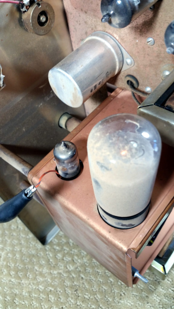
  Heathkit IG-42 Checkout – Part 2 Filed in Heathkit IG-42 on Mar.18, 2018 I put the IG-42 Signal Generator back on the bench to continue my initial inspection.  Today, I measured the voltages specified in the construction manual and measured the resistors (in circuit) to see if there were any obvious problems to address. Some of the tube pins were very difficult to access from the bottom side, so I stuck a wire in the top side on those pins and re-inserted the tube to get the readings.  This allowed me to continue without tearing the unit apart.     Cheater Wire for measuring tube voltages All measurements were made with the unit plugged into me variac transformer, with the voltage set to 115 vac, as originally specified for the IG-42.   115 vac input voltage The results are listed in the chart below… TUBE Pin1 Expected Pin1 Actual Pin2 Expected Pin2 Actual Pin3 Expected Pin3 Actual Pin4 Expected Pin4 Actual Pin5 Expec...

Kenpro KR-5400 Rotator Controller Repair

Image
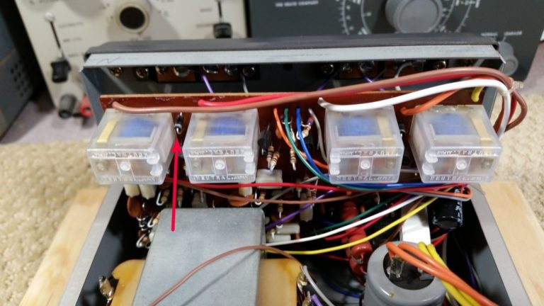
  Kenpro KR-5400 Rotator Controller Repair Filed in ANSR Tracker on Mar.14, 2018 At out last balloon flight, I discovered two problems with the rotator system.  The Elevation Meter was intermittent, and tapping on it would make the reading fall to zero, and tapping again would bring it back to the correct position.  This didn’t seem to be affecting the automatic control. I also found that the azimuth-right control was intermittent, and would not always move the rotor when pressed. This was definitely affecting the automatic control, as well as the manual control. I was able to recover each time by pressing the other controls for a short time, until the right rotation control worked again.   D18 Location I suspected poor connections in the control box for both of these problems.  Once I got home, I put the controller on the bench and removed the covers.  By probing on the cathode end of the diode across the relay coil, I was able to read 12 vo...

ANSR-115/116 High Altitude Balloon Flight

Image
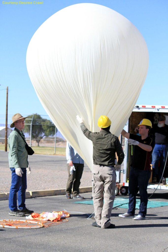
  ANSR-115/116 High Altitude Balloon Flight Filed in ANSR on Mar.14, 2018 On March 3rd, 2018, I helped out with the Arizona Near Space Research spring ASCEND flights.  Two high altitude weather balloons with payloads from several Arizona Colleges and Universities were launched from the parking lot of the grade school in Dateland, Arizona.   Inflating the balloon with helium   Student preparing payload for launch     Fly-Away   Intel-Man   Post-Launch My assignment this time was to preposition myself near the expected landing site, and get a head start on tracking down and finding the first balloon when it landed. I started out hanging out at the truck stop on Hassaympa Road and I-10 west of Buckeye, Az.  As the flight progressed, it became apparent that the balloon would land north of the Interstate, rather than South.  I repositioned myself to get closer to the revised estimate of the landing zone. I met up with Louis, W7...