Heathkit IG-42 Checkout – Part 2
Heathkit IG-42 Checkout – Part 2
I put the IG-42 Signal Generator back on the bench to continue my initial inspection. Today, I measured the voltages specified in the construction manual and measured the resistors (in circuit) to see if there were any obvious problems to address.
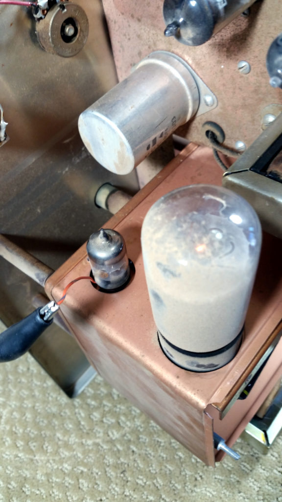
Some of the tube pins were very difficult to access from the bottom side, so I stuck a wire in the top side on those pins and re-inserted the tube to get the readings. This allowed me to continue without tearing the unit apart.
All measurements were made with the unit plugged into me variac transformer, with the voltage set to 115 vac, as originally specified for the IG-42.
The results are listed in the chart below…
| TUBE | Pin1 Expected | Pin1 Actual | Pin2 Expected | Pin2 Actual | Pin3 Expected | Pin3 Actual | Pin4 Expected | Pin4 Actual | Pin5 Expected | Pin5 Actual |
| 6AF4 | 65 | 89 | 10 - 30 Neg. | -13.8 | 0 | 0 | 5 - 7 AC | 5.9 | 0 | 0 |
| 6AV5 | 0 | 0 | 5 - 7 AC | 5.9 | 12 | 14.9 | 0 | 0 | 100 | 113.7 |
| 12AU7 | 60 | 72.4 | 1.0 Neg. | -1.3 | 2 | 1.95 | 5 - 7 AC | 5.9 | 5 - 7 AC | 5.9 |
| OB2 | 100 | 131.5 | 0 | 0 | 0 | 0 | 0 | 0 | 100 | 131.6 |
| TUBE | Pin6 Expected | Pin6 Actual | Pin7 Expected | Pin7 Actual | Pin8 Expected | Pin8 Actual | Pin9 Expected | Pin9 Actual | ||
| 6AF4 | 10 - 30 Neg. | -13.8 | 65 | 89 | ||||||
| 6AV5 | 0 | 0 | 0 | 0 | 100 | 131.5 | ||||
| 12AU7 | 100 | 117 | 30 | 35.5 | 33 | 37.5 | 0 | 0 | ||
| OB2 | 0 | 0 | 0 | 0 |
As you can see, the plate voltages are running quite a bit higher than they should be. Some of the other voltages are also moderately high.
I chased this down a bit further and found that the voltage output of the regulator tube 0B2 was sitting at about 131 vdc. It should be regulating to about 108 vdc. I understand that these tubes vary a bit from one to another, but 131 volts is quite a bit too high. The input from the rectifier is only 142 vdc.
So I pulled another OB2 from my Heathkit HG-10B VFO, to try it here and see if it corrected the problem. With the replacement tube in place, the regulated voltage is sitting at about 116 vdc. Still a little high, but probably usable. I’ll have to look through my boxes of spares to see if I can find another replacement.
For the second part of the testing today, I measured the resistors, without pulling them from the circuit. In that situation, I would expect that they should all read at or below their specified values. There were a few that were far out, and I found one that had the wrong size resistor installed. I don’t know why, maybe it was a mod to improve something. I’ll have to look into it further.
Here are the results of the resistance measurements…
| Resistor | Tube Pin | Measured Value | Filter Cap | Meter Switch | Fine Attenuator | Attenuator | Cable Term |
| 51 ohm | Not Present | ||||||
| 56 ohm | Inaccessible | ||||||
| 62 ohm | 51.4 ohm | ||||||
| 62 ohm | 50.6 ohm | ||||||
| 62 ohm | 56.7 Ohm | ||||||
| 62 ohm | Inaccessible | ||||||
| 470 ohm | 6AV5-3 | 458 ohm | |||||
| 510 ohm | 91.8 Ohm | ||||||
| 510 ohm | 95.9 ohm | ||||||
| 510 ohm | Inaccessible | ||||||
| 510 ohm | Inaccessible | ||||||
| 510 ohm | 268 ohm | ||||||
| 1K ohm | 12AU7-3 | 1 K | |||||
| 1K ohm 2 watt | 940 ohm | ||||||
| 1K ohm 2 watt | 932 ohm | ||||||
| 2.2 K ohm | 6AV5-1 | 2.3 K | |||||
| 4.7 K ohm | 4.47 K | ||||||
| 4.7 K ohm | 2.2 K | ||||||
| 10 K ohm | 12AU7-8 | 10.7 K | |||||
| 10 K ohm | 10.1 K | ||||||
| 10 K ohm | 9.17 K | ||||||
| 10 K ohm | 6AV5-8 | 9.9 K | |||||
| 15 K ohm | 6AV5-1 | 14.4 K | |||||
| 22 K ohm | 12AU7-1 | 23.76 K | |||||
| 47 K ohm | 12AU7-2 | 74.6 K (68K installed here) | |||||
| 100 K ohm | 6AF4-2 | 97 K | |||||
| 470 K ohm | 12AU7-7 | 970 K | |||||
| 1 M ohm | 12AU7-6 | 5.5 M |
There are a couple that I will replace (in red). Some of the resistors in the attenuator section were not accessible without tearing the unit apart. Given that those that were accessible were good, I’ll go with the assumption that the others are also good, at least until I see problems with the calibration.
Stay tuned for more adventures!


Comments
Post a Comment