Heathkit IG-42 Laboratory Generator – Initial Checkout
Heathkit IG-42 Laboratory Generator – Initial Checkout
I hooked up the Heathkit IG-42 Signal Generator to the variac on the bench and brought the voltage up slowly, watching for signs of overheating or failed components. There was a slight hum coming from the unit for the first couple of minutes, then it got better. I suspect that the electrolytic capacitors were recovering after having not been in use for some time.
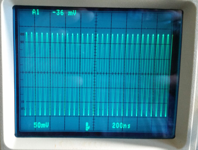
The IG-42 is rated for 100,000 uv output, with a 50 ohm output impedance. To check this against a known good source, I set up my HP 8640B signal generator for 0.1 volt output into the 50 ohm terminated input of my scope. 0.1 volt = 100,000 uv.

As the photo shows, I have about 0.28 vpp showing on the scope. To get the rms value from the vpp value, you first divide by 2, then multiply by 0.707
0.28 / 2 = 0.14
0.14 x 0.707 = 0.09898Â or approximately 0.1 vrms

So, I know that if I can get a similar 0.28vpp waveform from the Heathkit, it is meeting the output level specifications.
I set the IG-42 frequency to near mid scale (about 1.6 Mhz, in this case), and set the Microvolts control to x10K. So when the meter is at 10, then the output should be close to 100,000 uv, or 0.1 volt rms into the 50 ohm load.

When I looked on the scope, there was no output shown…

After tapping on various parts of the case, and wriggling the output cable, I found that if I held the output cable up at an angle, I could get an output. So it appears that the first issue is a poor connection on the connector that plugs into the IG-42. The waveform is not a great sine wave, but is typical of what I have seen from other Heathkit signal generators of this vintage.

On each of the 5 bands, I was able to obtain 100,000 uv output with the meter approximately at the full scale “10” value.
Band A – 100 Kc – 290 Kc


Band B – 280 Kc – 1000 Kc

Band C – 0.95 Mc – 3.1 Mc

Band D – 2.9 Mc – 9.5 Mc

Band E – 9.0 Mc – 31 Mc
So, what next?
I think I will begin replacement of all of the paper capacitors, along
with the electrolytics. I will replace the two caps across the line
input with X1Y2 rated safety capacitors. I still need to decide on
whether to replace the power cord or not. Since it is across the
transformer primary, and isolated from ground, it really doesn’t matter
which line is on hot or neutral. Particularly with the swap to the
safety caps across the line, from the original disc ceramic non-safety
rated caps. But I might still convince myself to do it.
The RG-58 cable that connects to the output will need to be repaired or replaced.
Finally, a cleanup of the cabinet and maybe knocking the dent out might be in order.
Stay tuned for updates…
Comments
Post a Comment