MMR40 S-Meter / Power Meter Circuit
MMR40 S-Meter / Power Meter Circuit
There is a simple S-meter/Power-meter circuit in the SPRAT Newsletter issue # 57 by Bill Bartlett, G4KIH.
It derives its S-meter component from the audio stages, and gets its Power indication from a simple RF probe.
To adapt this circuit to the MMR-40 took a little engineering, but it wasn’t too bad.
The original circuit is in Black above, with my modifications in Green. The modifications allow the use of a voltage regulator chip, rather than a 10 volt zener, which I didn’t have handy. They also fix a problem with the power indication, described below.
The first step was to figure out where to connect the circuit to the MMR-40. The MMR-40 kit has a trace available off of U8 pin 1, labeled Audio Line Out on the board. This is a good spot to pick up the audio for the S-meter, as it is before the volume control, so will not be affected by the setting of the volume. There is one problem that had to be solved with this point, though. More on that in a little bit.
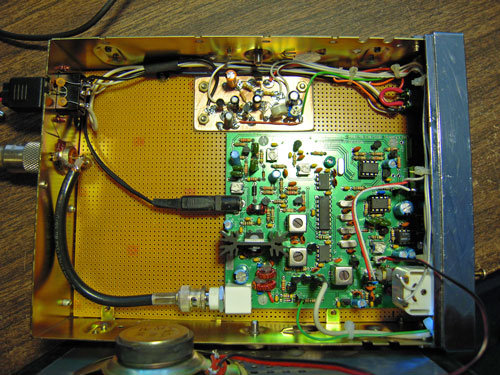
The RF probe is already built into the MMR-40, so it was not necessary to duplicate that on this board. I simply connected the input of the on-board RF probe to the antenna jack of the radio, and routed the DC output of the probe to the wiper of R6 on the S/RF meter board.
So the way this works is:
- Q1 amplifies the line level audio to provide a good signal for rectification by C3, D2 & D3.
- The output of D2 feeds the wiper of R5, which determines how much voltage/current is applied to the meter in S-meter mode.
- The RF Probe output feeds to the wiper of R6, which determines how much voltage/current is applied in Power mode.
- C4 is chosen to smooth out the meter movement to the degree that pleases you. I used 100uf.
Now, when I was building this, I made the Power circuit first. After hooking it up to the MMR-40, I was able to easily adjust R6 to indicate 5 watts out on the scale (about 3/4 scale).
Next, I built the S-meter portion. When this was hooked up, I was able to easily adjust R5 to indicate S-9 with 50uv input to the radio. I dropped the signal down to S-6, as marked on my Norcal Signal generator, and the meter read S-6 on the MMR-40! Cool!
Now, I put the dummy load back on, and transmitted CW again, but found that the S/RF meter was reading almost full scale. That was odd. I thought maybe there was some interaction, but after fiddling a while, decided that was not the case. I dug out my VF monitor and listened on the S-meter input while I was transmitting. There was a tone there in CW! Looking closely at the MMR-40 schematic, it is apparent that the receive muting occurs after the volume control. The signal before the volume control is not muted. I confirmed this by hooking up my microphone a speaking into it. The sound came out of my VF monitor connected to the Audio Line Out connection.
So I had to devise a circuit to mute the audio at the point where I was pulling it out of the MMR-40. I looked for a 2n7000 mosfet, so I could just duplicate the circuit that the MMR-40 uses later, but I didn’t have one handy. So I ended up using an extra 2n3904 bipolar transistor and driving the base with a 2.2K resistor from the RF probe input. So when I have power as indicated by the RF probe voltage, Q2 turns on, shorting the receive audio at the Line Out connection to ground. The 2.2K was just arrived at experimentally.
Finally, it was a little flakey on SSB, and I figured that the voltage to the base of Q2 was fluctuating with the voice peaks too much. I added a capacitor across the input to hold the circuit in for a few 10s of milliseconds. This worked out to be 22uf on my build.
Once the design was finished, I drilled 3 holes in the board and mounted it into the chassis.
And here is what the actual S-Meter looks like:


February 21st, 2013 at 10:32 pm
Hi nice s meter on your MMR-40. Do you have any true s meter design for the BITX20A by Hendricks? Ive been looking for awhile. Thanks Ron
January 22nd, 2014 at 11:03 am
Do you have any info on where the actual S-Meter (needle/dial) came from? I’m working on a similar project, and that meter face is *perfect*…
January 24th, 2014 at 4:03 pm
It’s from an old mobile CB from the 70’s or 80’s. Most of them had something similar.