More Volts from the LM7805 Regulator
More Volts from the LM7805 Regulator
I began development of an S-meter/Power meter interface for the MMR40 today.
The plan calls for a 10 volt supply, using a 10 volt zener diode for
regulation. Since I didn’t have a 10-volt zener on hand, I decided to
use an LM7805 regulator chip, but expand the voltage output to 10 volts
from its normal 5 volts.
To do that I used the method set out in an article by Sam Ulbing, N4UAU in the January, 1999 QST, page 45.
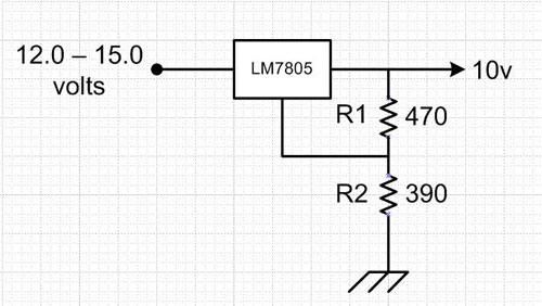
The basic circuit looks like this:
In the article, Sam gives the general guidance of setting the current through R1 at about 3 times the normal quiescent current for the 7805 regulator. He goes on to give the formula for the Output voltage from the circuit:
- Vout = 5 volts + (5v/R1 + Iq)*R2
- Vout = 5 + (5/470 + .003)*390
- Vout = 5 + (0.0106 + 0.003)*390
- Vout = 5 + (0.0136)*390
- Vout = 5 + 5.304
- Vout = 10.304 volts
The device he was using had a quiescent rating of about 8 ma, while the 78L05 (smaller, 100ma device) that I am using has a quiescent rating of about 3 ma.
So I created a spreadsheet with the pertinent formulas and breadboarded a circuit. I found that my voltages were slightly less, so I fudged the quiescent current value from 0.003 to 0.0026 to make the expected match the actual a little better. They were probably close enough already.
I suspect that for the range of values that are reasonable (say, 5 – 13 volts output) with an input at least 2 volts higher, the table should provide a good starting point for whatever voltage is needed. Just stick with the ones in which the IR1/Iq ratio is at least 3 to 1, and then pick ones with lower IR1 values for better efficiency.
78l05 Regulator Expanded Voltage Spreadsheet
Here is the test setup, with a 470 ohm/390 ohm divider, and a 220 ohm load (about 46ma):
And here is the result:


Comments
Post a Comment