Some MMR40 Fixes
Some MMR40 Fixes
While I was working on assembling the MMR40 into its chassis, I ran across a couple of problems.
After I hooked up the antenna connector jumper from the SO-239 on the back of the chassis to the BNC connector on the board, I did a quick check of power out. What’s this??? No Power?? How can that be???

Q9/Q10 circuit
So I started thinking about what had changed…
- Mechanical assembly – no chance for metal to metal contact
- Added several header pins for connecting Counter, RF Probe, etc – check for shorts
- Removed band range switch and added header pins for outboard switch – check connections
- Added power switch and wiring – check connections
- Added Digital Dial Counter – check header connections – check BFO setting
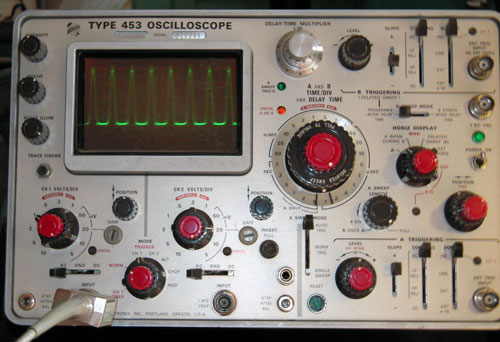
After checking all of this, I still had no power out. So next, I dug out the scope and meter.
- The DC voltages to the TX/RX switching sections were as specified in the manual.
- The DC voltages on Q10 and Q9 were normal.
- Q9 was producing what appeared to be a reasonable waveform on its collector, but I could not see it on Q10 Gate.
- The current in Transmit went up to about 90 ma, which seemed reasonable with no drive, but low with drive.
So it looked like I was missing drive from Q9 to Q10.
On the base of Q9, I had about 0.3 volts of RF signal:

Q9 Base signal ~ 0.3 vpp
Q9 Emitter had a similar waveform:

Q9 Emitter ~ 0.3vpp
Q9 collector had a strong signal into the transformer (about 40 vpp):
Q9 Collector ~40 vpp
The input to C48 had about 15 vpp (seems reasonable):

C48 Input from Q9 Circuit ~ 15vpp
When I checked the output of C48, I saw a very small signal (< 1 vpp). At this point it appeared that I may have had a bad solder joint, so I took the board out of its case, and resoldered the connections in that part of the circuit. Upon reassembly, I had the full 5 watts out.
Here is the Gate of Q10 when working correctly:

Q10 Gate ~ 10vpp
And the Q10 collector output into the transformer:

Q10 Drain ~ 40 vpp
And finally, the output from the antenna connector to a 50 ohm load:

Antenna Output ~ 45 vpp
So 45 vpp / 2 = 22.5 volts peak
22.5 * 0.707 = 15.9075
(15.9075^2)/50 ohms = 5.06 watts.


Comments
Post a Comment