MMR40 – Kit vs Homebrew L2
MMR40 – Kit vs Homebrew L2
After more comments on the MMR40 Yahoo Group, it is once again apparent that there are some significant differences between the Kit PCB and the Homebrew PCB pattern. This time, the winding of the L2 PTO coil is affected.
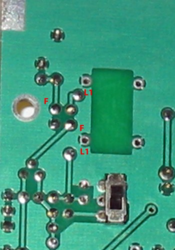
Here is the bottom of my Kit PCB:
And here is the same image, but flipped over so as to see through the board from the top side. This puts the PTO circuit in the upper right, as the Layout diagram is oriented.
And here is the Layout drawing in the Kit Documentation:
From all of this, it is apparent that
- The Top of L1 (Near the screw) connects to the Upper Left of the 4 pads used for L2, as viewed from the parts side of the board.
- The Bottom Of L1 connects to C8.
- The Top Right Pad of L2 (Marked with an F) connects to R1 and C9.
- The Bottom Left Pad of L2 connects to Q14.
- The Bottom Right Pad of L2 connects to ground.
All of this means that the L2 toroid wound as previously posted will drop right into place, with the Feedback leads going in the Top Right and Bottom Left Pads:
Now as for the Homebrew Version of the PCB:
Notice in this version of the PCB, the connections for L2 are different:
- The Top of L1 connects to the lower left of the four PCB pads.
- The Top Left Pad of L2 (Marked with an F) connects to R1 and C9.
- The Bottom Right Pad Connects to Q14.
- The Top Right Pad is grounded
So, it looks to me that the coil would need to be wound backwards from the Kit version of the coil, like this:
This puts the Feedback windings on the Upper Left and Lower right of the four L2 Pads, as appropriate for the Homebrew PCB version.


Comments
Post a Comment