MMR40 U3 LM386 Waveforms
MMR40 U3 LM386 Waveforms
In an attempt to help others that may be having problems in the audio stages of their MMR40, here are some waveforms and DC/AC voltages for the final audio amplifier stage U3.
All measurements are with volume control V2 full on, sidetone level control V5 full on, and with switch S1 in the wide position.
In general, you should be able to touch the input to U3 on pin 2 with your finger (or hold an uninsulated piece of wire to U3-2 with your fingers), and hear a 50 or 60 hz audio hum from the speaker from what you pick up around your house. If you cannot hear this hum, there may be something wrong in the audio stages, particularly U3.
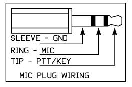
There is a second source of audio available on board, in the form of the sidetone oscillator that feeds into U3 pin 3 via the sidetone oscillator level control V5. To enable this tone (at least in the kit version) you must set the rig to CW mode my shorting the Microphone Jack Sleeve to the Ring. This is most easily done by inserting a mono 3.5mm plug into the jack, rather than a stereo one. Then the tip is shorted to ground to go into transmit mode.
With V5 turned all the way up, you will get maximum signal fed into U3 pin 3. About 20.5 mv rms as measured by my fluke multimeter on the lowest AC scale. This represents an input of about 8.4 nanowatts across the 50K input resistance of the LM386.
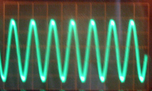
Here is the AC waveform in CW Tx mode on U3 pin 3:
It's a little fuzzy because I'm trying to hold the scope probe with one hand, and the camera with the other. I need to pick up my tripod from the ranch on my next trip up!
With this input on Pin 3, the output on Pin 5 is a little over 1.0 vpp:
This represents about 15.6 mw into an 8 ohm load.
1.0vpp/2 = 0.5volt peak
0.5 volts peak * 0.707 = 0.3535 volts rms
(0.3535 * 0.3535)/ 8 ohms = 0.0156 watts
So the power gain of this stage is about 10 * Log(0.0156/0.0000000084) = 62db.
For more reference, I tuned to an S-9 level signal from my NorcalQRP S9 signal generator. That resulted in the following waveforms:
Pin 1 - Gain Control Pin - No connections
Pin 2 - Receive Audio Input Pin. Fed from center post of volume control
I had a hard time getting this signal to hold sync, with a good sync it would be just a single sinusoidal waveform.
The 0.2 vpp signal represents about 0.1 uWatts across the 50K input impedance of the LM386.
U3 Pin 5 Output Pin.
The 5.0 vpp signal across the 8 ohm output gives us about 390mw output. So our gain in this case is about:
10 * Log(0.390/0.0000001) = 65db.
and Finally U3-8 Gain Pin
And here are the DC readings on each pin of the LM386, with No input signal:
DC:
- 1.35 volts DC
- 0.00 volts DC
- 0.00 volts DC
- 0.00 volts DC
- 0.00 volts DC
- 13.32 volts DC
- 6.77 volts DC
- 1.36 volts DC
And here are the AC readings on each pin with an S9 signal tuned in:
vpp is read from scope, vrms is read from Fluke DMM.
- 0.07 vpp : 26.4 vrms
- 0.20 vpp : 89.2 vrms
- 0.00 vpp : 0.00 vrms
- 0.00 vpp : 0.00 vrms
- 5.00 vpp : 2.01 vrms
- 0.00 vpp : 0.0 vrms
- 0.00 vpp : 0.00 vrms
- 0.15 vpp : 54.0 vrms


Comments
Post a Comment