Posts

Hex Beam Installation

Image
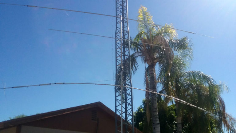
  Hex Beam Installation Filed in Antennas, on May.18, 2017 After giving up on my 35 year old Cushcraft A4, I ordered a Hex Beam from NA4RR.     Trap Dipole, VHF and UHF antennas installed I Settled on this beam after reading many reviews and getting recommendations from friends. I like the simple, no-trap design, and the coverage of the WARC bands. While a traditional tribander might give a little more gain, I think the tradeoffs are worth it. I ordered the beam, and received a shipping notice the next day. It would take approximately 1 week to arrive from Florida to Arizona. So we loaded up the truck and headed to the mountains to cool off for a few days. After returning to Mesa, the beam arrived a couple of days later, one day past the original estimate provided by UPS. It arrived in two packages, one with the fiberglass supports and center mast, and one with hardware, wires and the baseplate. Since it had arrived at dusk, we had to wait until the next m...
Cushcraft A4 Repair (Fail!)

Image
  Cushcraft A4 Repair (Fail!) Filed in Antennas on May.18, 2017 Shortly after I had repaired my Cushcraft A4 tribander beam the last time, I noticed that it appeared to have a loose connection somewhere. Especially when the wind was blowing, I would hear something that sounded a little like static crashes, or pops in the receiver. This was especially noticeable on 20 meters, but was apparent on all bands.   A4 coming down the tower About a year ago, I climbed up and removed the short coax that made up the balun, which connected to the long feedline on one end, and the beam on the other. It was very weather beaten, and looked to have poor connections at the antenna end.   Bad coax connections After examining the coax, I decided to just build a new one. This just involved installing some terminal ends on one end of a new piece of coax, and a PL-259 connector with a barrel at the other end.   New Coax Balun cable After building and testing the balun in the ...

TS-430 RF and IF Signal Paths

Image
  TS-430 RF and IF Signal Paths Filed in Vintage Radio on Dec.28, 2016 I’ve had some questions from readers about where to obtain the color annotated schematics for the TS-430 that I used in some of my previous posts.   Violet line indicates the missing SSW signal. I created the schematics from a photo of the corresponding pages from the service manual for the rig. After taking a photo with my digital camera, I used the SnagIt program on my computer to add color lines representing the various RF, IF and Oscillator paths. Some of the other paths (voltages and such) were already annotated in red on the original schematics in the service manual. Anyway, here are the annotated schematics for the RF and IF sections, which were the only ones that I modified in this way. Enjoy… RF_Unit IF_Unit

8640b Power Supply Repair

Image
  8640b Power Supply Repair Filed in 8640b on Nov.02, 2016 Early in the repair cycle of the 8640b, when I had just finished the brass gearset installation, I ran into a problem during the first power up after reinstallation of the deviation and range module. When I powered up the unit, I saw a flash from under the main board, and the unit came up with no led frequency display. I suspected that I had lost one of the power supplies. After finding the manual for the generator, I saw that there were 3 power supply boards with led indicators on them to indicate the various voltages were being generated.   5v indicator I found that the 5v indicator was not lit. Looking at the schematic of the board, I tracked down that it should have some relatively high voltage DC coming in on pins 15 and 9 of the module ( or pins 1 & 2 of the rectifier module). It had nothing coming in. I saw in the schematic that it was fed from a rectifier board. Since this had easy access, I...

8640b Fine Tune Repair

Image
  8640b Fine Tune Repair Filed in 8640b on Nov.01, 2016 Another item on the 8640b refurbishment project was the broken Fine Tune control. I could rotate the control from the front panel, but it had no effect on the frequency generated. After removing the bottom cover, I could see the problem. The Oscillator Module was missing the shaft that connected the fine tube knob with the control on the rear of the main oscillator   Shaft missing The shaft should be near the top of the picture above. I started the repair by removing the Main and fine tune knobs.   Main and Fine Tune controls     Knobs removed There is a module beside the main oscillator that needs to be removed, as it is connected to the wires from the back of the main oscillator. I just removed the two nuts/washers securing it, and pulled it up out of its card slot (it has an edge card connector). Then, it will lift out with the rest of the main oscillator module.   Loose module Next, I...