TS-790 9600 Baud Mod
I was working on a 2-meter FM radio that I have recently acquired. It had a low deviation problem, which requires a method of measuring deviation in order to fix it and adjust it to specs.
While I do not have a service monitor or other direct way of measuring deviation, I happened to recall that I had made a 9600 baud modification to my old Kenwood TS-790 that I have had since the late '90s.
The modification brought out connections that allow direct FM modulation (no pre/de-emphisis), and a direct discriminator output.
If I could connect an instrument to the discriminator output, I could use my HP 8640b RF Generator to feed an FM signal to the radio at various deviation settings, and record AC voltage measurements of the audio output from the discriminator. These could be plotted on a chart and used as a reference to measure the deviation of other radios when they transmit an FM signal.
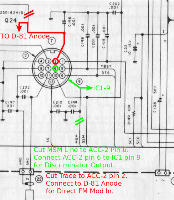
Digging through my old documentation, I found a schematic on which I noted the modification.
For Direct FM Transmit audio (To the Main side Transmitter):
1. Cut the trace to Pin 2 of ACC-2.
2. Connect a coax from ACC-2 Pin 2 to the Anode of D-81 via a 1K resistor.
3. Ground the coax to Pin 4 of ACC-2.
For Discriminator Output (From the SUB Receiver):
1. Cut the trace to Pin 6 of ACC-2.
2. Connect a coax from ACC-2 Pin 6 to IC-1 Pin 9.
3. Ground the coax to Pin 4 of ACC-2.
I connected my 8640b signal generator to the TS-790 and input a strong signal at the frequency that the SUB receiver was listening to. I used my scope to measure the AC RMS voltage of the discriminator output.
I modulated the generator steady at 2 khz deviation and swept the audio frequency from 200 hz to about 5 khz. I noted that the deviation varied just a little ( about a half-kilohertz) between 2 and 5 khz. So I can account for that in my measurements if necessary.
Next, I set the modulating frequency at a steady tone of 700 hz. I then varied the deviation of the incoming signal from a few hundred hz to 5 khz.
the results are in this table:
As you can see, the output is pretty linear throughout the range of deviations, making it pretty easy to measure the deviation of incoming signals.
I am please with the result. This will come in handy when adjusting FM transmitters in the future.


Comments
Post a Comment