Kenpro KR-5400 Repair
We did a balloon launch at the Maricopa Hamfest just before Halloween this year.
My job, as usual, was to ready the video payload, and track the balloon in order to get a live feed of the video from the balloon.
I always pull out my tracking system and assemble it in the days before an event, to make sure that I have everything I need, and it is all working. When I set everything up and did a full test run on Monday, everything worked fine.
On the day of the flight, we set up the system as normal, and initial tests of moving the antennas up and down, and through their full range of motion indicated that we were ready to go.
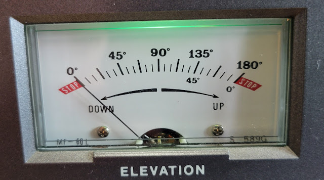
But when the balloon went up, Murphy hit. My elevation rotor was not getting a good indication on either the meter of the control box, nor my tracking software. This was intermittent, as sometimes toggling the controls seemed to make it work for a while.
I muddled through by manually controlling the antenna, sometimes needing to search for the balloon video downlink. It was tricky, but we managed to get good video through probably about half of the flight.
After the flight was over, we tore down, and I hauled everything home. A couple of days later, I had some time to troubleshoot.
I set the system up on my bench, and started having a look.
First I checked for obvious bad connections by wriggling cables and knocking on the side of the box to see if the symptom went away. That didn't find anything.
Next, I checked for signal to/from the elevation rotor. I found that there was no 5-volt feed to the rotor, and thus no return voltage to indicate position.
I ohmed out the cable connecting the control box to the rotor, and it appeared ok. Next I checked on the back of the control box, and found the 5-volts missing there, as well.
OK, time to go inside the control box.
A look at the schematic shows that the 5-volts is derived from a 7806 regulator, and sent directly out the rotor connector at the back of the box.
The 5-volt source is shared with the azimuth position indicator in terminal A-1. This was working, so something was wrong with the path from where the 5-volts splits off at the current limiting resistors R-8 and R-9.
I found a small brown wire on the 5-volt supply terminal, and traced it back to where it connected to the control board. Nearby was a brown wirewound resister. The top of the resistor had the 5-volt supply present. So I thought, maybe a bad solder joint on the resistor.
Sure enough, when I wriggled the resistor, it was clearly loose from the board on the other end.
I removed the board from the meters by removing two screws that connected to each meter. That freed the board up so that I could flip it over. Close examination showed the cold solder joint on the solder side of the board.
I removed all of the old solder and applied new solder to the joint, cleaning it with isopropyl alchol when I was done. After some preliminary tests, I put everything back together and now have a working system again.


Comments
Post a Comment