ERC-4 Interface & My HyGain Ham-IV Rotator Controller – Part 3
ERC-4 Interface & My HyGain Ham-IV Rotator Controller – Part 3
Installation
My HyGain Ham-IV rotator was built in 2016. The control box has changed in its layout over the years. In the documentation from the CD, the picture of the Ham-IV shows that the meter board is installed vertically behind the meter. In my version, it is installed horizontally (parallel to the chassis surface) on the switch side of the cabinet.
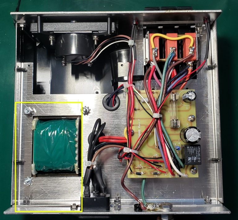
Since this is where the ERC-4 was supposed to be installed, I had to find a new location. I chose to install it in the space under the transformer. There really didn’t seem to be many options, but this location worked out well. There is plenty of space between the transformer and the cover of the cabinet.
[ ] Choose a location to install the ERC-4 into the controller cabinet.
There was some challenge to drilling the holes on the back plate. I didn’t feel like there was enough room to drill from the inside of the cabinet, so I had to find a way to mark the holes from the outside.
The ERC board needed to be installed upside-down. That is, the component side needed to be facing the transformer, in order to fit in the cabinet here. I decided to use one screw from the AC input plug to hold one side, and drill out the other holes according to the template included with the board.
I ended up cutting the template small, to just include the needed hole locations, and flipping it around so that the non-printed side faced out. Keep in mind that this is a mirror of the other side. Just be sure to line up the DC Jack hole and the USB Jack hole with the way the board is to be installed. If I had been thinking more, I would have punched little alignment holes from the printed side of the paper to serve as more clearly marked guide points. Instead, I lifted the paper up enough to allow the light to show the print from the other side, then used that as my guide point. Of course, when the paper was laid back down, I could no longer see the print from the other side. The result was that one of my holes was off by a quarter inch or so. I worked around it, but could have avoided the problem by poking a little hole in the paper for each location from the printed side before laying it down to the surface of the controller.
[ ] Remove the outer screw from the AC Power inlet.
[ ] Place the hole template on the chassis in the correct position.

As you can see, the DC Jack hole is a little elongated to correct my error…
By the way, do you see the slide switch in the top left of the photo? That’s not shown in my schematics that came with the rotator. It grounds out the meter indication from the rotor, making it read far left 180 degrees on the meter. It needs to be switched to the outside (left in this case) in order to operate correctly.
[ ] Mark and drill the holes for the DC Jack, USB Jack and outer L-Bracket mount.

Since the ERC will be installed upside-down, you have to remember that the position of the terminal strips is also backward.
The relay outputs are wired across the normally open contacts of the corresponding switches in the rotor controller. Note that on the ERC board, there are 3 terminals for each relay. The middle terminal in each case is the common lead. The terminal closest to the outside of the board is the normally-closed position. The terminal closest to the inside of the board is the normally open position.
So for both the CW and CCW relays, you want to use the middle terminal and the terminal closest to the inside of the board. For the Brake relay and the metering circuit, there are only two terminals, so no guessing there… I have outlined the terminals in yellow rectangles in the photo below. You can see which have wires connected.

The CW terminals are wired to the switch marked CW in the controller. The exposed top of the switch is the common lead, and the first lug down on the back of the switch is the normally-open lead. These are the leads you want to wire the relay normally open contacts across. You can see that my black leads are on the top lugs of the switches, and my blue leads are on the first lug down on the back of the switches.


As indicated in the installation instructions included on the CD, the blue circles #1 and #2 indicate the CW connections.
The Yellow circles #1 and #2 indicate the CCW connections.
The Red circles #1 and #2 indicate the Brake connections.
[ ] Position the ERC in its mounting location, but do not bolt it to the chassis yet.
This will allow you to access the screw terminals to install the wiring.
[ ] Connect wires from the CCW Normally Open terminals on the ERC to the switch lugs Yellow #1 and #2.
[ ] Connect wires from the CW Normally Open terminals on the ERC to the switch lugs Blue #1 and #2.
[ ] Connect wires from the AUX Normally Open terminals on the ERC to the switch lugs Red #1 and #2.
[ ] Connect wires to the UM (Metering) terminals on the side of the ERC Board.
[ ] Route the metering wires down through the rubber grommet, and leave enough lead to reach the slide switch on the back of the controller.
[ ] Flip the controller over to access the other side
[ ] Connect the signal wire from the ERC to the meter indication pin 3 (Green Circle #1) on the Rotor Controller cable connector.
[ ] Connect the ground wire from the ERC to the ground lug (Black Circle #1) located just under the slide switch.

[ ] Secure the ERC Board to the back of the chassis, using the L brackets and screws. Note that one screw will come through the power connector mounting hole. You will need a longer M3-10 screw to reach all the way through that hole.


Comments
Post a Comment