ERC-4 Interface & My HyGain Ham-IV Rotator Controller
ERC-4 Interface & My HyGain Ham-IV Rotator Controller
Having recently added a Flex Radio 6400 in my hamshack, I’m making progress on being able to operate the radio from my office in the house, while the radio is installed in my garage workshop. The radio makes remote operation very easy, with nearly all functions adjustable over the ethernet link.
The next step is to be able to turn my rotator from the computer in my office, while the rotator control box is located in the shop. In order to facilitate this operation, I purchased an ERC-4 rotator controller from Vibroplex. I have another one of these that I use with my balloon tracking station, and it has worked well with my Kenpro 5400 AZ/EL rotator.

My HF rotator is the HyGain Ham-IV. It is an azimuth only rotator, with push levers to rotate CCW or CW, and a middle lever for a brake release. The ERC-4 controller supports all three of these operations, and sequences the brake to release before attempting to turn the rotator, and reapplying the brake after the rotation is complete.
The instructions that come on the CD with the ERC-4 were easy enough to follow, but I thought a little more detail than, “populate the board with all the parts” might be helpful. So here are some pictures and some notes on how I built and installed the ERC-4 into my HyGain Ham-IV controller. This is not intended as a replacement for the instructions on the CD, but rather a supplement that may help organize and clarify your build.
Construction
The package arrived 4 days after I ordered it from Vibroplex. I had ordered the previous ERC controller from Germany, and that too, had arrived quickly from Europe. But since Vibroplex is now the US Distributor for this product, I ordered it from their website.

I did a quick inventory and sorted the parts, placing like-items together.

I started construction with the smaller components, so that the board would lie relatively flat on the bench while I was working on it in the beginning.
[ ] Install the 8 pin header onto the IC3 USB board in the component side.
If it has one side of the pins longer than the other, solder the short side to the IC3 board.
*** Sorry, no picture here. I forgot to take one.
[ ] Install the crystal Q1
[ ] Install the two 22pf capacitors C1 & C2

[ ] Install the socket for the microcontroller IC1 *** Note the half-circle divot goes to the top side near pin 1***
[ ] Install the 100nf (104) capacitors C3 – C9
Note in the picture below that I missed installing C9, as I had miscounted the capacitors. I will install it in a later step.

[ ] Install the 1uf Tantalum capacitors C11 – C13 *** Note the polarity, Neg lead to the left on all 3 ***

[ ] Install Jumper JP1
[ ] Install the 20k-ohm resistors R1 – R3

[ ] Install the 39k-ohm resistor R4

[ ] Install the 10uh inductors L1 & L2

[ ] Install 1N400x Diode D1 *** Note the proper polarity cathode to the left***
[ ] Install the P6KE33CA Diode D2 *** No polarity concerns on this one ***

[ ] Install the 7805 Voltage Regulator *** Note the flat side orientation ***

[ ] Install the 1-Amp mini fuse F1

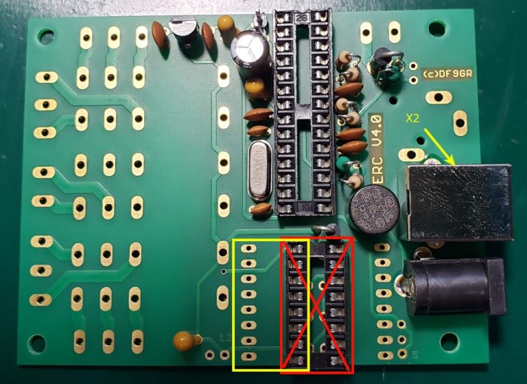
[ ] Install the socket for IC2 *** Note that the half-circle goes up here as well ***
I made an error on this step and installed the socket into the wrong set of holes (Red X). The correct location is the next set of holes over. So after I discovered this far down the install, I corrected it. Don’t make this mistake. It goes where the yellow rectangle is in the photo below.

[ ] Install the 100uf electrolytic capacitor C18 ***Note the correct polarity, Negative lead on the left***

[ ] Install the power jack J1

[ ] Install the USB Jack X2
[ ] Install the Terminal Blocks X3 – X8 *** Be sure to face the open end out, so that you can insert wires easily***

[ ] Install Relays K1 – K3

[ ] Install the IC3 USB module
Note that this is where I recognized my error in placing the IC2 socket, and corrected it here. Otherwise IC3 would not fit…

[ ] Install the two “L” brackets, using screws, lockwashers and nuts
I installed these on the component side of the board, as that fit my Ham-IV controller the best. Of course they go on the end with the USB and power jacks.


Comments
Post a Comment