3018 CNC for PCB Milling?
3018 CNC for PCB Milling?
I have started learning how to mill PCB boards using a benchtop CNC Router.

In the past, I have used a chemical etching method to create custom PCBs for some of my projects. While it was generally successful, there were some problems with the process.
- It was messy. Storing and mixing the chemicals used in the etching process inevitably led to some splashing of the chemicals on clothing, workbenches and other items of value. This was especially a problem when the Ferric Chloride solution was used, as it stained everything it touched. Using a muriatic acid/hydrogen peroxide solution was cleaner, but still problematic.
- Disposal of the chemicals was a problem. Even after heavy dilution, one worries about the environmental effects of the waste chemical disposal. After etching, the chemicals had an added quantity of copper. That complicates things. Until very recently, the city only allowed hazardous waste disposal on a very limited basis.
- I used the printer transfer method, in which you print a mirrored copy of the copper traces using a laser printer or a photocopy machine. That copy is then melted onto the unetched PCB blank using a laminator. That worked pretty well when I could use our good HP laser printers at work. The problem I had after retirement was that my personal laser printer at home used a toner that melted at too high of a temperature to achieve good results. I could have bought a suitable laser printer, but decided that was wasteful, as my old printer still worked well for its intended purpose. So I ended up printing out a PCB pattern and taking it to the local Staples Store and having a photocopy made there. That was kind of a pain.
- Drilling the holes in the PCB was difficult to do by hand. It resulted in many tiny drill bits being broken, and often tore out the copper trace around the holes.
So I decided to try milling PCBs using a cheap CNC router as well as a laser cut stainless steel stencils. After a little bit of research, I decided on the 3018 platform that used the aluminum platform, which seemed like it would be sturdier than the Bakelite models that have recently appeared.
The box of parts arrived in just days, much sooner that I expected. Further inspection revealed that it shipped from New Jersey, rather than China.

The parts looked to be of pretty good quality.
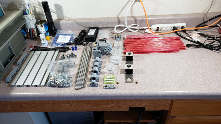
However, I could not read anything on the small CD that they included, which was supposed to have instructions and software. I tried on two different linux machines and one Windows 10 machine. They all said there was nothing on the disk. I could not see anything etched onto the disk when I examined it under a magnifying lens. So I think they sent a blank disk.
I plowed on with assembly, using a mixture of instructions I found from other providers of similar machines. One particular youtube video was especially helpful.
The most stressful part was installing the included ERC-11 collet onto the spindle. The E-Bay ad had said that the collet would not simply slip on, but would need to be “shrink-fitted” onto the shaft. So I put the spindle motor into the freezer for a couple of hours, and heated the ERC-11 collet in the toaster oven to 425 deg F. Then I brought them together in my vice, and squeezed the collet onto the shaft of the spindle. It was a pretty hard squeeze, much harder than I was expecting. After letting it cool and tightening the setscrews (not that they needed it), I put the spindle assembly back into the 3018 holder, and spun up the spindle with an engraving bit in it. At high speed, it appeared as a single tip, rather than two or more, so it appears that the shaft was not bent during the installation.

Once the CNC was built, I went around and tightened all screws that I had installed, measuring for square everywhere I could.

Milling a PCB requires 3 major steps…
- Creating your circuit board design, and exporting GRBL files that represent the structure of the board in PCB layers, holes and outlines. I have the free Fritzing program for this part.
- Creating the step-by-step machine instructions called “g-code” from the GRBL files. I use the free Flatcam program for this step.
- Sending the g-code to the CNC controller. I use the open source “Candle” program for this step.
I found copies of the open-source or free software that most of these cnc machining used, and loaded them onto my laptop in Windows 10. My laptop already had the CH340 serial drivers installed, as those are common with Arduino boards, so I did not need to install that.
I found version 1.1.7 of Candle, which is the software used to send “g-code” commands to the controller board. It was in a zip file, and installation was simply unzipping it into a folder, and placing that folder where I wanted it. The software is started by simply clicking on the .exe file, wherever it happens to end up.
FlatCam and Fritzing have installation programs for Windows.
After installing Candle, I started it up. With the CNC plugged into my laptop USB post, I was getting an error indicating that Candle did not see it.

I checked in the Device Manager for may laptop, and saw that it was installed on Com port 8.

But Candle was looking for it on Com Port 12. After changing the com port in Candle to 8, it connected to the CNC machine.

Next, I tried moving the spindle back and forth, up and down. There was no movement, and it appeared that there were no commands being sent when I pressed the various jog buttons. I found that on the first boot, the 3018 came up in a locked state (presumably for safety), and I was able to unlock it using the unlock button. Now, pressing the spindle button did turn the spindle on and off, but I still could not jog the spindle in any direction.
Next, I tried moving the spindle using manual instructions entered into the command box at the bottom of the screen. Starting with the spindle located in the approximate middle of its movement range in all axis, I pushed the buttons to set this spot to zero on the X, Y and Z axis. Then I sent…
- G1 X10 F3200
- G1 Y10 F3200
- G1 Z10 F3200
These commands all moved the spindle. So I knew the hardware worked, but the Jog buttons were just not sending the commands.
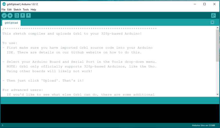
After some searches on the internet, I found that Candle version 1.1 to firmware version 0.9 of the grbl control board that was pre-installed did not support the jog button commands. So I searched for and found version 1.1 of the firmware and installed it using my Arduino IDE.
Installation of the new grbl firmware was pretty easy. I downloaded the new version and unzipped it into a folder. Then I used the library utility in the Arduino IDE to import the grbl library.


Finally, I had to tell the IDE to use the new library…

Then I loaded the example sketch, compiled it and sent it to the 3018 controller. Everything with that went well.

With the new grbl firmware installed, I could now control the movement of the spindle in all directions. However, the Y axis was reverse from what I needed. When the “UP” arrow is pressed, the platform should move toward you. When the “DOWN” arrow is pressed, the platform should move away from you. Mine did the opposite.
The Candle instructions included a list of parameters that could be changed to configure the machine. After saving a copy of the original parameters by typing “$$” into the command box, then selecting it all and copying it to a notepad file, I found that typing $3=2 in the command box inverts the direction of the Y axis, as required.
Next, I found some sample g-code files from SainSmart to test the basic router function.

I followed very detailed instructions found on the Electronic Unicycle Forum (don’t ask how I ran onto that site) to attempt to mill my first PCB.
I used a set of PCB GRBL files that I randomly discovered that seemed to have some close spacing and small traces. These were a good test of the machine’s (and my own) capabilities.
My first try was rather dismal. Many of the traces were way too thin or gone completely. Halfway through the milling, a bolt fell out of the bottom of the spindle. The spindle holder had been pre-assembled, and I hadn’t checked them for tightness.

I made several more tries over the next few days, with gradually improving results. Making sure everything was tight (I had also forgotten to tighten the carving bit in the ERC-11 collet) helped a lot. Then making sure to correctly create and use a heightmap for the PCB made a big difference.


A Heightmap is the result of a procedure that measures the height of the surface of the blank PCB above the platform it is clamped to. You wouldn’t think it would make much difference if the board is 0.2mm higher in one spot than another, but with the copper being so thin on these boards, it makes a big difference. Creating and using a heightmap compensates for those tiny differences.
After all of this, I was still not getting acceptable mills.

Finally, I ran across a youtube that suggested that due to the inherent wobble in the spindle of these cheap machines, you should input a tool width of 0.2mm, rather than the 0.15mm that I had calculated for the carving bit I was using. That made a big difference in that Flatcam now compensated when creating the milling paths to avoid getting too close to the tiny traces.
So finally, I have some good results.

I’ll make a couple of postings showing my process flow through Fritzing, Flatcam and Candle to create good PCBs here. Of course, everyone will need to experiment and find their own settings, depending on their particular PCB blanks, bits, and machine tolerances.


Comments
Post a Comment