Nano_VNA Testing
Nano_VNA Testing
This year, one of my Christmas presents was a Nano_VNA (Vector Network Analyzer). These are like an antenna analyzer on steroids. You can check the SWR of your antenna through a range of frequencies, and get detailed information about the antenna impedance, including whether it is inductive or capacitive at a given frequency. This information is useful in developing matching networks for your homebrew antennas.
The Unit has the additional capability to inject a swept frequency range through a device and detect how much gets through the output of the device under test. So it should be great for sweeping filter networks (Low Pass, High Pass, Band Pass, Notch, etc…), as well as cavity filters used in repeaters.
The Nano_VNA covers all frequencies between 50 khz and 900 Mhz. That is a pretty good range, and covers the VLF bands, all of the HF bands, 2 meters, the 220 Mhz band and the 70 cm band.
Just to get familiar with it, I connected it to my K4HEX Hex beam, which should have resonant spots on the 20, 17, 15, 12, 10 and 6 meter bands. In addition, a friend with the same antenna told me that he uses his regularly on 2 meters with good success, so I swept that band, as well.

20 Meter Results
I started by setting the Nano_VNA up to sweep the 20 meter band, with a little overlap to surrounding frequencies. I set the Start Frequency to 13 Mhz, the Stop Frequency to 15 Mhz. Then I calibrated the VNA at that range. I don’t know yet if I need to calibrate for each different band to get valid results, but felt it was better to calibrate over a small range, rather than the whole 900 Mhz that the VNA can cover. It only uses 101 steps, regardless of how much frequency you are sweeping, so if we sweep the entire 900 Mhz, each step would be approximately 9 Mhz from the next. That could skip entire ham bands. By setting my range to only cover 2 Mhz over 101 steps, each step covers approximately 20 khz. Much more reasonable.
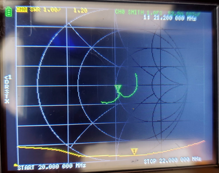
My first result shows a Return Loss for the 20 meter band, which is another measure of SWR, often preferred by RF engineers.

The Yellow trace shows the Return Loss, at -23db, which equates to about a 1.14:1 SWR ratio. Anything more negative than -10 dbm is better than a 2:1 SWR.
The green line shows how the impedance of the antenna changes as we sweep through the range. This is plotted on the Smith Chart, and that is a whole lesson unto itself. Suffice it to say that the center “cross hairs” represents a 50 ohm load, with no inductive or capacitive reactance. So the closer you get to that spot, the better off you are. Anything above the center line represents an inductive load, while anything below the centerline represents a capacitive load.
To convert from Return Loss to SWR, the formula from (https://www.allaboutcircuits.com/tools/vswr-return-loss-calculator/) is:

But most people just refer to a chart, such as available at:
https://www.amphenolrf.com/vswr-conversion-chart/
Going to our next photo, this is what the SWR looks like when graphed on the 20 Meter band.

The first line up from the bottom represents a 2:1 SWR, and each vertical line represents 500 khz. So you can see that the entire 20 meter band falls under a 2:1 SWR.
And here are plots of the other bands, all under 2:1 SWR over the entire ham band of choice.


And as you can see below, even the 2 meter band is well covered by the antenna. Of course, much of this may be due to the relatively high cable losses of the LMR-400 over 100 feet at that frequency, but it does poke a signal out.

Now, I understand that I can run a program on my computer and import data from the Nano_VNA to create much better charts. I haven’t gotten that far yet, but look forward to it (especially if I can get the programs to run in Linux!).
This should be easier to use to develop the matching network for my planned 160 meter inverted-L (sort of..) with the folded counterpoise in lieu of an extensive radial field at my site in Mesa. I’ll post again when that happens…


Comments
Post a Comment