Arduino Due and the SD Card Reader
Arduino Due and the SD Card Reader
The next board to test with the SD Card Readers is the Arduino Due.
This is a little different sort of beast, more powerful. But there are some differences with other Arduinos that can get us in trouble.
Differences between Due and the Mega:
| Microcontroller | AT91SAM3X8E (Due) | ATmega1280 (mega2560) |
| Operating Voltage | 3.3V | 5V |
| Input Voltage (recommended) | 7-12V | 7-12V |
| Input Voltage (limits) | 6-16V | 6-20V |
| Digital I/O Pins | 54 (12 provide PWM output) | 54 (15 provide PWM) |
| Analog Input Pins | 12 | 16 |
| Analog Output Pins | 2 (DAC) | 0 |
| DC input per Pin | 3 – 15mA (see chart) | 40 mA |
| Total DC Output Current | 130 mA | 200 mA |
| DC Current for 3.3V Pin | 800 mA | 50 mA (up to 150 mA, if no FTDI) |
| DC Current for 5V Pin | 800 mA | 200 mA |
| Flash Memory | 512 KB all available for the user applications | 128 KB (4 KB used by bootloader) |
| SRAM | 96 KB (two banks: 64KB and 32KB) | 8 KB |
| Clock Speed | 84MHZ | 16MHZ |
- The Due CPU operates at 3.3V, while most Arduinos CPUs operate at 5.0v
- Connecting higher voltages to I/O, like the 5V commonly used with the other Arduino boards will damage the Due.
- The Due is not as heavy duty as most other Arduinos
- The Due has 1 dedicated SPI port, and 4 multipurpose USART/SPI ports.
- The SPI port is only routed to the 6 pin header.
- This header is not used for In Circuit Programming on the Due.
- The Due does not have any EEPROM
- The Due uses a ARM chip instead of an AVR
- might cause problems with some libraries that only support AVR.
- Many older shield are not compatible with the Due
- The Due has the ability to act as a USB host for peripherals connected to the SerialUSB port.
- The Due is capable of higher resolution on analog reads and writes
- It can support up to 12-bit ADC and PWM resolutions.
- The Due has expanded functionality on its SPI bus.
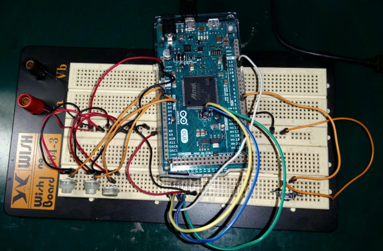
Considering these differences, I connected the Due up to our SD Card test circuit as follows:
SD Card Testing Setup
| SD Card Pin | Arduino Due Pin |
| VCC | POWER 3.3V |
| GND | POWER GND7-12V |
| MISO | SPI-1 |
| MOSI | SPI-4 |
| SCK | SPI-3 |
| CS | DI-10 |
| Other Connections | |
| Kill Switch | DI-2 |
Once everything was hooked up appropriately, I plugged the Due into the USB port on my laptop. After a few seconds, another new com port showed up for the Due.
I set the IDE up to compile for the Auduino Due on the programming port (nearest the power connector). Then I selected the matching Com Port.
After setting up the Due, I loaded the CardInfo program. Again, the only change for any of the Card Reader programs was to specify the correct Chip Select Pin that matched the hardware wiring (pin 10 in this case).
The program compiled with no problems. The compiler output looks a little different…
It shows the progress of uploading the program, then the progress on verifying the upload.
The program works fine, as did all of the other Card Reader programs that I tested (as in prior posts on this subject).
Finally, I changed the SD Card out to a 32GB card, and ran CardInfo on it. No problems there…
So, it was not as difficult as I thought it might be.


Comments
Post a Comment