Tektronix 2645 Oscilloscope Repair – Part 1
Tektronix 2645 Oscilloscope Repair – Part 1
High Voltage Power Supply and Beam Finder
During my evaluation of the Thunderbird Hamfest Tektronix 2465 scope, I found two problems:
1. The display was shrunken to about a 2×2 graticule size. This seemed to go away after the scope was powered on for some time.
2. The scope was displaying a diagnostic error indicating a problem with the ram memory. The ram is battery backed up, and the lithium battery that holds the memory was determined to be bad (about a half-volt, instead of the required 3.3 volts).

I did some initial troubleshooting and ordered a capacitor in the low voltage power supply. The ESR of the cap was reading a little high, although the voltages all appeared to be normal. I also ordered a replacement lithium battery from Mouser.
When the parts arrived, I replaced the “bad” cap, which had no effect on the symptoms. Since the rest of the caps in the low voltage supply have a normal ESR value, and the voltage outputs are good, I’ve decided to keep them in service until something specific happens to convince me to change them.
Once the low voltage supply was re-installed back into the scope, I started some more in-depth troubleshooting. I decided to look at the high voltage power supply A9 module. The service manual has waveforms and test points to look at.
I first took a look at the waveforms at the various test points on the module. The idea was to get a read while the unit was in the “shrunken screen” mode, and then take a second look when it was in the “normal screen” mode. Hopefully a significant difference would show up, leading me toward the problem component. This turned out to be a red-herring, but I’ll post the waveforms here, so anyone interested can reference them if necessary.

The parts placement that I have in all 3 of my manuals do not match my board exactly, but they are very close. The only test point I had trouble finding was TP-72. On my board, there are only 3 components in that column under the high voltage module on the right. So I couldn’t find r-1941. Instead, I found CR-1930 right next to it, which is supposed to be the same electrical point. So I used that.

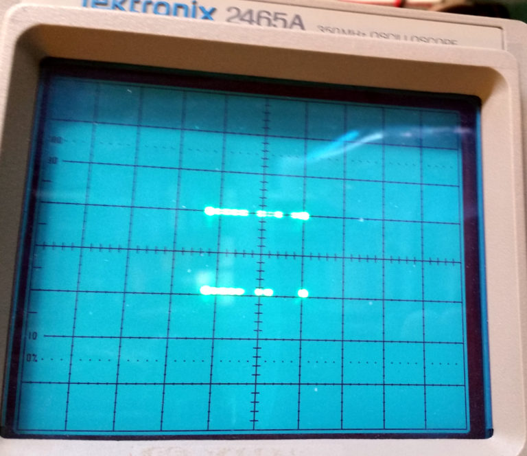
TP-69 is labeled “Quad Pole #1 +
The bad state looks like this:
The good state looks like this:

The manual says these should have a period of about 3ms, whereas I have a period of 1.6 us. I’m not sure what’s up with that. The only change I see is an increase in peak-peak voltage, which I attribute to my touching the intensity control between the two test runs. So no significant change.
TP-70 is the high voltage oscillator output. Both states look good to me, and pretty much agree with the manual’s specs.


TP-71 is the secondary off the high voltage transformer. This looks good in both states, as well.
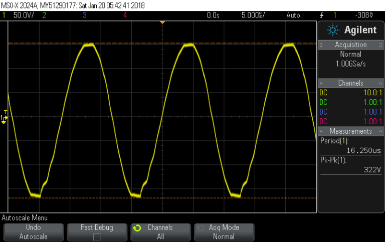

TP-72 is the input to the high voltage module. I was concerned about the high frequency oscillation on the negative swing of the waveform, but it remains after the normal display is on, so I guess I won’t worry…


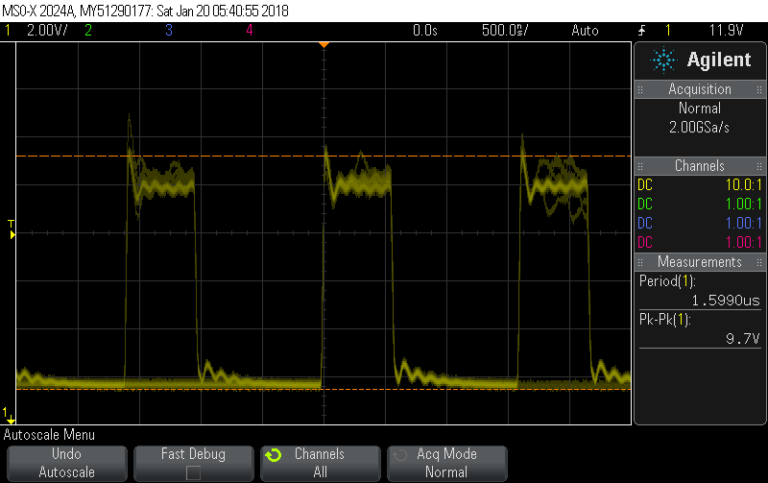
TP-73 feeds grid 1 of the CRT. This is another one that the manual says is 2ms, but comes up as only 1.5us on my scope. No significant change from bad to good state.


TP-74 is a warm up delay. I could see the voltage rising on this point after turn on, but didn’t bother setting up a test to capture the waveform. Both states acted the same.
So, it appears that there is not a problem with the high voltage power supply affecting the display size.
After running through the tests in the bad state, I waited about an hour for the display to heal itself, as it had done last week. That never happened this time.
I began to thump the various circuit boards in an attempt to see if the problem was a bad connection. When I thumped the main board near the front of the scope, the display briefly went normal, then back to shrunken. A little more prodding, and I narrowed it down to… The beam finder button!

Aghhh… How can this be? I had worked the beam finder button a few times when I first noticed the symptom, but it had no effect on the display at that time. But now, after working it on and off maybe a dozen times, I could get it to stay good, until I pushed it again.
A little De-Oxit D5 on the button did the trick. I sprayed a little into the switch, worked the button a couple dozen times, sprayed it again, worked it again, and now all is good with the display size.
Onward to the next problem: replace the lithium battery and attempt to calibrate the scope to save the needed parameters.
Stay tuned…


Comments
Post a Comment