Tektronix 2465A Oscilloscope Repair – Part 3
Tektronix 2465A Oscilloscope Repair – Part 3
Low Voltage Power Supply Measurements Calibration
The first part of the calibration procedure is to adjust the 10-volt reference voltage on the low voltage power supply, and check all of the other voltages from that supply. This procedure is described in the service manual for the scope.
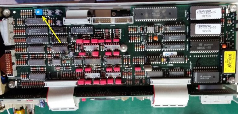
All of the voltages are available for checking on a test socket of the A1 Main board. It is the J119 socket.

Tektronix LVPS Adjustment Procedures
And a closeup…

Pin 1 is on the bottom left, in this picture. R-1292 on the Low Voltage Power supply is adjusted as close as you can get to 10.00 volts. Mine adjusted there exactly.

Then you check that the rest of the voltages on J-119 are within specifications. They all were, in my case.

The next step is to adjust the DAC Reference output voltage to make the range equal to 2.5 volts total. You do this by rotating the delta-t control full ccw (until the DAC voltage no longer changes), and noting the voltage, then rotate the control full cw until the voltage no longer changes, and note the second voltage. They should be near -1.25 and +1.25. Try to get the sum of the absolute values as close to 2.5 volts as you can get by adjusting the DAC Ref R-2010 on the A5 control board. I had to go back and forth a few times but eventually ended up with -1.295v and +1.205 volts (sum absolutes to = 2.50 volts).


Comments
Post a Comment