Heathkit C3 Condenser Checker – Restoration
Heathkit C3 Condenser Checker – Restoration
Ok, I’ve received my order from justradios.com. Now it’s time to replace almost all of the capacitors and a good number of the resistors in the C3 Condenser Checker. We’ll follow that up with a basic checkout, and finally finish up by testing the caps and resistors that we pull out.
Here is what we started out with…
We’ll replace all of the 22k resistors, along with the 10k resistor on the range switch. We’ll also replace the two 0.01 uf caps that are paralleled to create the 0.02 uf reference capacitor on the range switch. The precision resistors on the range switch will stay in place, as they are still well within specs. The two high-value resistors on the back of the 1629 Eye tube will also remain, as they are still good.
In the photo above, the resistors and the one pair of capacitors have been replaced. I also found one of the orange wires had been cut, spliced together and wrapped with electrical tape. This was replaced with a single wire (the black one from the range switch to the pot on the right).
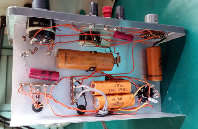
Here is the underside of the chassis before we replaced anything.
Here, we are going to replace all of the capacitors, and the resistors on the back of the power factor switch.
And here it is with the parts replaced…
The 0.25 uf cap on the right hand side was a challenge, because the lead length of the new capacitor would not reach where it needed to. I could have moved it to the other side of the chassis and placed it on the other end of the orange wire, but decided to splice it in the original location, so as to be more intuitive for the next guy that works on it.
The 0.05 uf line capacitor was replaced with the rectangular safety cap in the middle of the screen. Everything else was just a 1-for-1 replacement.
While I was replacing parts under the chassis, I found a couple of bad solder joints that I fixed. Here are the bad ones…
At this point, I applied power to the unit (again slowly increasing AC from my variac). Everything came up as expected.
I measured the DC voltages on the leakage test voltage divider string. They were all nice and close, with the exception of the 25 volt position. Here, the reading was still around 40 volts dc. On examining the circuit, I can see that the leakage voltage is set by a resistor divider network consisting of a 10K resistor in series with four 22K resistors. The current through this divider network is set by a 47K resistor at the rectifier tube to about 4.5ma.
4.5 ma through at 10K resistor gives us a voltage drop of 45 volts. So it appears that either the label on the front of the unit incorrectly designates 25 volts, and should say 50 volts; or the design is incorrect. As the instruction manual specifies a leakage voltage of 25 volts, I choose to believe that the design is incorrect.
To make the correction, I set up a spreadsheet to check the various voltage drops across the divider network, and played with it until I arrived with reasonable voltages in all leakage test positions.
| Â | R1 | R1a | R2 | R3 | R4 | R5 | R6 | R_Total | Source Volts | Current Total |
| Resistance | 5600 | 5100 | 22000 | 22000 | 22000 | 22000 | 47000 | 145700 | 655 | 0.00450 |
| Ind. Voltage Drop | 25.2 | 22.9 | 98.9 | 98.9 | 98.9 | 98.9 | ||||
| String Voltage Drop | 25.2 | 48.1 | 147.0 | 245.9 | 344.8 | 443.7 | ||||
| Watts Dissipated | 0.11 | 0.10 | 0.44 | 0.44 | 0.44 | 0.44 |
I find that if I replace the single 10K resistor with a series 5.1K and 5.6K resistor, that I can arrive at very near 25 volts at the first tap, while maintaining the correct values at all of the other taps. I bodged this in as a test, and it worked. So I sent an order for some 1-Watt, 1% resistors from China. They are on the slow boat coming over. When I get them in, I’ll post again with the results.


Comments
Post a Comment