Heathkit C3 Condenser Checker – How it Works Part 2
Heathkit C3 Condenser Checker – How it Works Part 2
In my pre4vious post,
I described how the basic Wheatstone Bridge works, and how that circuit
was utilized to find resistance and capacitance values in the Heathkit
C3 Condenser Checker.
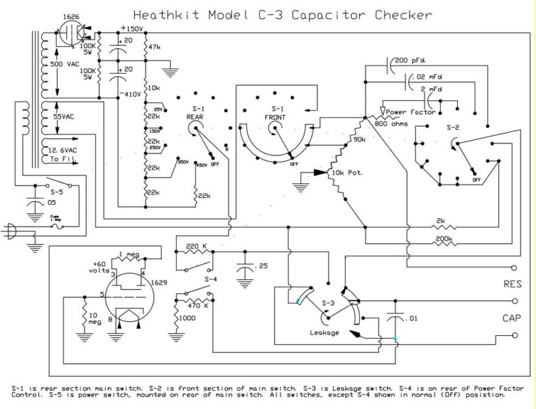
In this post, we will look at the schematic diagram in two different forms to show some details of the circuit.
The drawings in this post were found on the internet. I modified them by tracing out the circuits with some color lines to show functionality. I don’t know the source of the original drawings.
First, we can look at the bridge operation while measuring low value resistances.
In the schematic above, we show the source voltage for the Wheatstone Bridge in orange.
It is a 55 volt AC sine wave picked off of a winding on the power
transformer. This same source is used for all resistance and
capacitance value measurements, but is not used for leakage
measurements.
The bottom of the winding is connected to the bottom of the bridge
circuit. The top of the winding connects to the common tap of the
rotary switch S-1. As the switch is rotated from Off to the first 5 On
positions, the winding is connected through the contact to the junction
between the 90K resistor and the 10K potentiometer. At the same time,
the 90K resistor is shorted out, taking it out of the circuit.
The green line indicates the common path for the resistance or capacitance measurement part of the circuit that drives the Eye tube. A sample voltage is picked off of the banana jack that is common to both resistors and capacitors under test. This voltage is applied to the grid of the Eye tube.
In the schematic above, we have added the bridge circuit (in blue)
for the Rx1 position, for measuring low value resistances.The 4 legs of
the bridge circuit consist of the two parts of the 10K potentiometer
(one on each side of the wiper), the 2K “known” resistor, and the
unknown resistor that goes across the “RES” banana jacks.
The measurement is made between chassis ground (which is common with the
left side bridge junction at the 10K pot wiper), and the junction
between the 2K known resistor and the unknown resistor. Tuning for a
null voltage between these points balances the bridge and allows us to
read the value on the front dial.
In the Rx100 position, a 200K known resistor is selected by switch S-2, instead of the 2K resistor. All other connections remain the same, and the scale on the front dial is read with 2 extra zeros tacked on.
To read low value capacitors, we use the circuit below…
Here, the left side of the bridge (in blue)
still consists of the 10K pot split between the two legs. While the
right side has the 200 pf “known” capacitor and the unknown capacitor
connected across the CAP banana jacks. The measurement point is the same
place as with resistance measurements.
The next position for the 0.5 uf scale simply selects the 0.02 uf known capacitor, rather than the 200 pf known cap. All other connections remain the same.
The next position selects the 50 uf scale. This is much the same circuit, except that the known capacitor is now a 2 uf cap. In addition, since large electrolytic capacitors of the time were sometimes inefficient, the 800 ohm “Power Factor” potentiometer is placed in line with the known capacitor to allow you to compensate for the extra resistance in these capacitors. At the same time, it allows you to measure the efficiency of the capacitor under test, based on how far you have to rotate the control to get the widest reading on the eye tube.
Finally, we have the last capacitance scale – the 1000 uf scale. In this position, the same 2 uf known capacitor, along with the 800 ohm power factor pot is used on the right side of the bridge. In addition, a change is made on the left side to add an extra 90K resistor in series with one side of the 10K pot. This is accomplished by removing the short that was across that resistor for all of the other scales This moves the range enough that we can read capacitors in the 20 to 1000 uf region.
So you can see how a relatively simple switching arrangement allows us to read a wide variety of devices.
Below, you will find two schematic drawings from the heathkit manual that show the same thing as the drawings above, but in a less intuitive way.
R x 100 Scale
C 0.005 uf:
0.5 uf Diagram:
50 uf Diagram:
1000 uf Diagram:
In my next post, we will discuss the Leakage Measurement portions of the circuit.
Migrated Comments:


September 23rd, 2018 at 11:17 am
Nice information. Just purchased a Heathkit C-3 as I am restoring old tube radios and needed a cap checker that would test under caps rated voltage for leakage.
Thanks for the great description. Need to find your next post on Leakage Measurement.
Paul
September 23rd, 2018 at 10:04 pm
Hi Paul. Glad you enjoyed the article. Here is a link to the Leakage Measurement section…
http://www.wb0smx.net/?p=2322
Good luck with your C-3.
73…