Heathkit C3 Condenser Checker – How it works
Heathkit C3 Condenser Checker – How it works
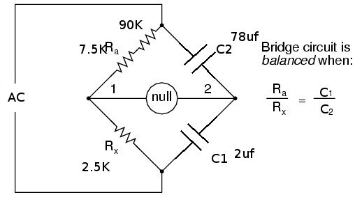
The circuit description in the C3 manual does not go into many details about how the circuit works. Although the circuit diagram is not drawn in the familiar layout for one, it may be traced out to arrive at a reasonable resemblance to a wheatstone bridge circuit. (credit diagram below to https://goforaplusplus.wordpress.com/2011/09/08/wheatstone-bridge/)

This is a common circuit used in test instruments for measuring resistance, capacitance and inductance. It works by forming two voltage dividers that share a common source voltage. Then the voltage in the middle of each leg of the network are compared while one leg is adjusted in value. When the two voltages are equal, then the ratio of the first leg is equal to the ratio of the second leg, resulting in a null voltage between the two.
Please note, in the diagrams below, that the Ra and Rx values on the left would normally represent the adjustable leg and the unknown leg of the bridge. But in my case, I didn’t notice the reference labels until I was far into the production of this blog entry. I am too lazy to go back and change all the drawings, so in my case, Ra and Rx represent the adjustable potentiometer that spans both sections of the leg on the left, while the unknown value is R1 on the upper right.
In the C3 bridge, the two resistors on the left are actually one 10K ohm potentiometer, with the adjustable middle leg connected to the metering circuit. Thus, as the pot is varied, the values of the two resistor legs on the left are varied proportionally. That is… as one resistor is reduced by 1K, the other resistor is increased by 1K. So each side of the pot can move from near zero ohms to 10K ohms, while the other side moves in the opposite direction.
To see how this works, we can look at the circuit as it is set up for measuring small value resistances:

In this circuit, Ra and Rx represent the potentiometer connected to
the dial on the front of the checker. It is shown at the center of its
rotation, with 5K on each side of the wiper.
R2 is the “known” resistor in the other leg (right side) of the bridge.
You can see that since Ra = Rx (5K ohms = 5Kohms) that the center wiper
of the pot will be at half of the supplied voltage. In our case, the
supplied voltage is 55 vac, so half will be about 22.5 vac.
If we then place a 2K ohm resistor in the R1 location (our “unknown” resistance), then that half of the bridge will have the same 1:1 ratio as the left side (2K ohms = 2K ohms). So the voltage at terminal 2 of the metering circuit will also be at half of the supplied voltage, or 22.5 vac.
So, if terminal 1 is at 22.5 vac and terminal 2 is at 22.5 vac, the difference between the two terminals is zero, and a null is found.
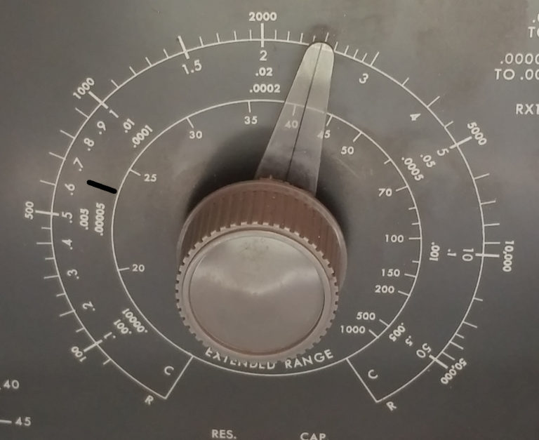
You can see from the front panel, that the middle of the resistor scale (which is where the pot is sitting when it is at half scale), is marked as 2000 ohms (at the top).

Now, lets try a different “unknown” capacitor…

In this case, we put our unknown capacitor into the R1 position, while R2 remains at 2K. When we adjust the potentiometer on the left hand side, we move it until there is no voltage difference between terminal 1 and terminal 2 of the metering circuit. This indicates that the bridge is balanced, and the ratio of resistances on the left hand side equal the ratio on the right hand side. This happens to have been found with Ra set to 2.5K ohms and Rx set to 7.5 K ohms. so the ratio is found by:
2500/7500 = 0.333
So now we can determine that the value of the unknown R1 resistor = 2000 * 0.333, or about 667 ohms. Or we could just look at where the dial on the front would be pointing, about 1/4 scale on the left side, 1-1/2 marks past the 500 reading (where the black mark is).

Continuing on, let’s look at the upper end of the scale.
Let’s try another “unknown” resistor:

In this case, we find a null when Ra = 7.5K and Rx = 2.5K. So the ratio is found by:
7500/2500 = 3
This time, we can determine that the value of the unknown R1 resistor = 2000 * 3, or about 6000 ohms. Or we could just look at where the dial on the front is pointed, about 3/4 scale on the right side (one mark past the 5000), where the dial would be pointed.

For higher resistances, we replace the 2K known resistor at R2 with a 200K known resistor. The ratios work out the same, you just have to add two zeros to your reading on the outside scale. So the dial would be read as 200,000 ohms when pointing straight up.

What about capacitors? Well since we are using an AC voltage for the source, we can replace the right hand side of the bridge with a known and an unknown capacitor, and have it work the same way. The only trick is that since capacitive reactance is an inverse function of capacitance, then the ratio is flipped. That is, when capacitance increases, capacitive reactance decreases. So we just flip the formula for the ratio to match.

Let’s see how this works out with a known 200 pf capacitor in the place of C1. You can see that when the unknown capacitor happens to be 200 pf as well, then the left side will be balanced when the pot is right in the middle of its range, with 5K on each side. The dial would indicate .0002 uf, or 200 pf.


And to show the some more ratios on the left and right sides of the scale…


Now the tricky part…
Heathkit wanted to be able to measure higher value capacitors, but didn’t want to spend extra money for an extra “known” precision capacitor to handle the higher range. So they decided to cheap out and add an extra resistor on the adjustable side of the bridge. This shifts the balance point way out, and allows measurement of capacitors in the 20 – 1000 uf range. This is the very innermost of the dial scales, labeled “Extended Range”. Here is what the circuit looks like.

This happens to work out such that when the pot is in the center of it’s range, and the circuit is balanced, the unknown capacitance will be about 38 uf.

You can see how it still works…
(90K + 5K)/5K = 95K/5K = 19:1 ratio
38 uf / 2 uf = 19:1 ratio — the bridge is balanced with the pot at center range.


(90K + 2.5K)/7.5K = 92.5K/7.5K = 12.33:1 ratio
24.666 uf /2 uf = 12.33:1 ratio — the bridge is balanced.

And on the upper end of the scale…
(90K + 7.5K)/2.5K = 97.5K/2.5K = 39:1 ratio
78 uf /2 uf = 39:1 ratio — the bridge is balanced.

In my next entry, I’ll provide schematics annotated to show the path of the various measurements.


Comments
Post a Comment