HP 8640b Signal Generator Gear Set Replacement
HP 8640b Signal Generator Gear Set Replacement
Back in April of 2016, I bid on a Hewlett Packard 8640b signal generator to upgrade my test bench at home. This was from a local seller, and I won the bid for $115.00 + $20.00 shipping, for a total of $135.00. I figured for that price, I couldn’t go wrong. In working condition, these typically run about $500.00, depending on condition.
When the unit arrived, it was not packed great (they used packing peanuts, instead of snug foam), but it was double boxed, and there appeared to be no damage in shipping.
I plugged in the unit and brought it up slowly on the variac, in case there were shorts that might cause further problems in the unit. To my surprise, the unit came up and appeared to mostly work. I could not turn the FM Deviation knob through all of it’s ranges, and the generator indicated that the deviation was out of allowed limits when I turned the FM modulation on. Also, the FM Deviation vernier knob was broken completely off, and the Fine Tuning control was inoperable. But the unit was generating RF on all bands up to 512 Mhz, and the output level seemed to be well calibrated.
I removed the bottom cover to investigate why the FM deviation knob would not go into all levels. I found the dreaded “broken gear set” syndrome on the FM Deviation and Range module. I wasn’t too surprised at this, as it is a very common failure in these generators. Seeing that it was in pretty good shape aside from that, I looked for info about repairing the module.
Here is a PDF guide for the following steps, adapted from Hewlett Packard’s Service Sheet D.

I found several sites that mentioned replacing the broken gears, with some using gear sets from Italy (cast resin gears), and some mentioning brass gear sets. I wasn’t too keen on replacing one set of plastic gears with another, and I was skeptical on how long the plastic used in the resin gears would last in this application. I ran across the callsign and email of a ham here in the states that manufactures a set of brass gears that had good reviews in the Yahoo HP Agilent group. I figured I would have this generator the rest of my life, so I contacted the supplier. Paul Koretko is his name, and his email address is hglent@frii.com. His amateur callsign is WA0BAG.
(Yahoo Group Membership required for Yahoo links…)
https://groups.yahoo.com/neo/groups/hp_agilent_equipment/conversations/messages/60535
I was pleasantly surprised to hear back from him the same day, specifying the cost, and the process of ordering and fulfillment. Yes, it is costly. I paid more for this gear set than I had for the whole generator. But like I said, this is a lifetime repair, and I figured that even if I sold the generator later, the brass gear set would be a good selling point, and I could likely recover my costs.
I put the deposit down (with Paypal) for the man to begin the process by ordering the needed parts for his end. A few days later, he contacted me back, letting me know that they were ready to ship, and I sent him the remainder of the cost via Paypal. A couple of days later, I received the gear set in the mail.
I was just getting ready to leave for vacation at that time, so the 8640b and its new gear set sat on the bench for a couple of months until I got around to the installation, which began in October.
Paul included service-sheet-d for the Model 8640b from the repair manual. And here is a a9-parts-breakdown
In Step 1, I was to set the PEAK DEVIATION and RANGE switches full ccw. As my gearset was broken, I could not do that. As an alternative, I took pictures of the various contact locations on the switches connected to the gearsets, and intended to duplicate those positions when I reassembled the unit. That worked out well.
After removing the two switch bushing nuts that secure the A9 module to the front of the faceplate in step 4, I was able to remove the A9 module from the chassis by unplugging the two ribbon cables from the A9 module at the sockets of the A13 main board assembly underneath. They pull straight up.
I took pictures of the position of the shaft coupling as I decoupled it from the A10 divider/filter assembly. This is a detented switch shaft that should not be moved while the repair is going on. Don’t loose track of the nylon coupling between the A9 and A10 assemblies.
With the A9 module removed from the generator, I was able to place it on the bench to continue work on the gearset replacement.
The next step (6) had me unsolder the three wires on the back of the potentiometer.

Once this was done, I was able to pull the pot out the back of the unit. There was no retainer ring on mine, as the shaft had been broken off.

Once the pot was removed, the next step was to remove the rotor at the rear of the switch (step 8). When the retainer clip is removed, the spring and flat washer are loose on the shaft. Removing the coupler from the end of the shaft allows all the parts to come off.


(Step 10) With all four screws removed, the assemble may now be split apart at the gear sets.

Next step (11) is to remove the T-shaft and combination gear. It just slides off of the solid shaft.

The adjoining combination gear on the solid shaft may be removed after loosening the allen screws.


The next step (13) is to remove the spur gear from the hollow shaft that is still in place. Make note of the position of the spur gear on the shaft, as it will need to be replaced in the same position, so it is not too tight or loose. The spur gear is the one on the left side of the following picture…

At this point, you can reverse the procedure to start installing the brass replacement gears.
First, I slid the combo gear and spur gear into place The combo gear is barely above the PC board, to prevent scraping. Tighten it in place..

To replace the planet gears on the T-shaft, I had to remove the retainer clip from each side. There didn’t seem to be much of a groove for these to fit into, so take pictures to note location. With the clips removed, the nylon gears slide off, and the brass gears slide on. The the retaining clips are reinstalled.

Next, the T-shaft slides onto the solid shaft.
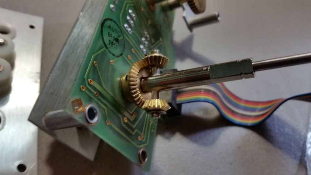
With the T-Shaft in place, the other combo gear will slide on and mesh with the planet gears. Tighten the second combo gear on the shaft.

Next, reinstall the gear mounting plate and A9A2 assembly, using the four screws on the side of the module. Once the unit is back together, the rotary switch can be reinstalled. To do this,you should now be able to rotate both switches fully ccw. With that done, also take the time to make sure that the A10 filter assembly switch that this module couples to in back is also in its full ccw position. Once everything is in position, reinstall the plastic wafer, spring and flatwasher on the back of the unit.

In the picture above, the switch is NOT is it’s full ccw position. When in full ccw, the switch should have the contacts positioned in a vertical line at the top, as shown below. I forgot to take a picture of it before reinstalling the A9 module to the generator, so I pulled it back out and took photos in the correct positions.

And the front wafer switch contacts should be roughly vertical at the bottom of the switch in the full ccw position…

Finally, I reinstalled the FM Deviation Potentiometer.
With the A10 module switch in the fully ccw position, it should be positioned something like this…

So I reinstalled the module, using the bushings on the front face, and plugged in the ribbon cables to connect it to the main board. When I applied power, I saw a flash underneath the unit, and there was no frequency displayed. I later traced that to bad solder connections from the power transformer to the PC board that it connects to. Once this was fixed, all worked well.
Here are a couple of links to relevant discussions on the Yahoo Groups site and the Antique Radio Forum.
https://groups.yahoo.com/neo/groups/hp_agilent_equipment/conversations/topics/60387
http://antiqueradios.com/forums//viewtopic.php?f=8&t=242165
The next job was to fix the potentiometer shaft to allow changing the FM deviation. I’ll cover that in the next post.
Migrated Comments:


June 14th, 2017 at 10:36 am
Does any one have a solution for the lost contacts that are staked on the clear plastic discs?
This 8640 not only has cracked gears but it also is missing most of the contacts on the discs.
I repaired many 8640’s as an HP employee and have seen this contacts missing alot but I had all of the parts available back then maybe 20 years or more ago.
Thanks!
June 14th, 2017 at 2:51 pm
There is a Yahoo Group called HP/Agilent Test Equipment where they discuss this problem in various threads.
https://groups.yahoo.com/neo/groups/hp_agilent_equipment/info
Some suggest finding another piece of HP test equipment and using parts from it to fix the 8640. Apparently, some had the same switch types.
When replacing the individual contacts, most recommend using a 2-part epoxy to firm them up. I was lucky in that my wafer switches were in good shape.
Good luck, Randy P. WB0SMX
February 16th, 2019 at 7:33 pm
I see different gears than original – pictures 10 , 11 , 12 , 13 & 14 plastic .
versus 15 , 17 & 18 – new brass gear is not a combination gear , or does not match plastic in 10,12,13,14 ?
Thanks John
February 17th, 2019 at 7:57 am
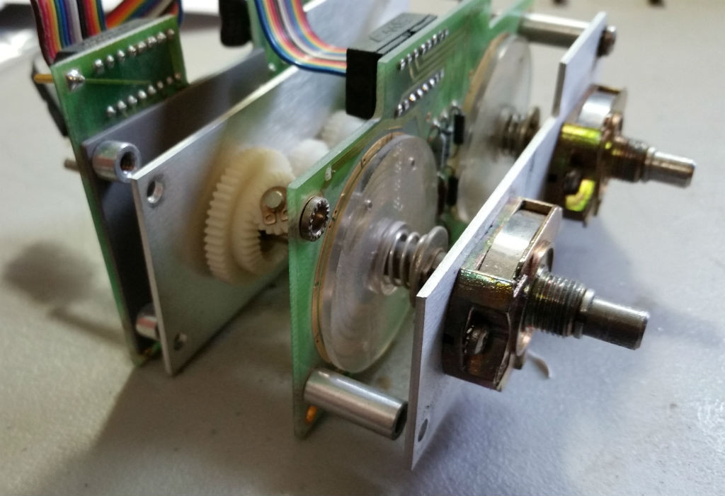
Hi John. I think I see where the confusion might be. In photo 1 at the top of the page, I can see that the plastic gearset with the combo gears appears to have 5 levels. From the printed circuit board, a flat gear, beveled gear, two combo gears in a tee configuration, another beveled gear and another flat gear.
On the new brass gearset (shown complete in photo 18), there are only 4 levels. From the printed circuit board, a bevelled gear, two combo gears in a tee configuration, another beveled gear and a flat gear.
So the brass gearset is missing the flat gear down against the printed circuit board. It appears that on the plastic set, that gear had no function, as it did not mesh with any other gears. I suspect that this was just a matter of HP using an existing part that had the beveled gear, which they used, molded with the flat gear, which was unused.
It’s been a while since I did the mod, so I don’t recall my thoughts at the time, but that’s what the pictures tell me. I can tell you that the brass gearset from Paul works great as installed, as I have had no problems with it.
Thanks for the comment, an 73… Randy wb0smx