ANSR Ground Station Tracking System
ANSR Ground Station Tracking System
In support of the Arizona Near Space Research group, I have agreed to set up a new ground station for tracking the balloon flights. We do this in order to point directional antennas at the balloons as they float across the state on their missions. I had done this about 10 – 12 years ago with a PIC processor programmed to read the telemetry from the balloon beacons and calculate the azimuth and elevation to point the directional antennas at the balloon for optimum reception of live video feeds.

When I left the ANSR group, another member (Gary, K7GGG) took over that responsibility. He developed a C# program to do those same functions on a PC. That program talks to a rotator controller interface to move the antenna array. My new system will initially use his software.
I started out by trying an RTL-SDR dongle that I had ordered via EBay as the receiver.

That worked fine with some programs (APRS-IS, AWGPE), but Gary’s program does not have the interface necessary to work with the dongle. So I knew I needed a device that would supply serial data to Gary’s program. My old MFJ-1270 TNC fits that role nicely.
The MFJ TNC needs an audio input from a radio to work. As an experiment, I was able to feed the audio from my RTL-SDR dongle, out through the headphone jack of my computer, to the TNC. This worked fairly well, and can be a good backup as necessary. To simplify the setup at the launch sites, I decided that a dedicated radio would be better. My next attempt used my old Radio Shack PRO-2040 scanner as the receiver. Using this receiver, I got good decodes on almost all packets received on the local APRS network.
At this point, I began to throw together a box that would hold all of the gear, leaving them mostly connected together between flights so that I wouldn’t have to rebuild the station each time. I used left over 1/2″ plywood from another project, and made slide-in shelves for the various components, in case I needed to work on them or replace them. That turned out to be a good decision. I’m not too proud of the woodwork, but I was in a hurry to get it done before the next flight, so I made a few woodworking errors that show up in the final product. Maybe someday I’ll redo it, but for now, it works.

At the top of the cabinet, the MFJ-1270 TNC is mounted to a shelf. The next shelf down holds the Radio Shack PRO-2040 scanner that is used as the receiver. Under that is the Kenpro KR-5400 Rotator Controller. The bottom shelf is hidden below that, and holds a 300-watt inverter to supply 115 volt AC for the rotator controller and anything else that I plug in.
After testing the scanner as a receiver, I decided that a dual band transceiver might be useful for this purpose. I found a Leixen VV-898 dual band transceiver on Amazon for $63.00, that sounded like it would work great.

After receiving the order and hooking it up, I found that the receive is quite noisy, and does not allow for very good reception of APRS. I checked the sensitivity, and it is plenty sensitive (about 0.2 uv for 10 db sig/noise ratio), but when hooked to an antenna, there is a lot of interference/noise on the received signals. I believe that the filtering is very poor, resulting in a lot of inter-modulation distortion. In the end, I found that on an antenna that my scanner can decode received packets better than 90% of the time, this radio only had about a 10% success rate. This would not do.
So, not having a spare dual band radio to use, I decided to just use my old scanner as the receiver. I ended up mounting a second audio output jack on the rear of the scanner, so that I could feed both the TNC and the computer with received audio at the same time. That way, I can use several programs on the computer to read the telemetry and provide various functions.
The box marked “ERC” is the “Easy Rotator Controller”, ordered from Germany. This takes a serial command from the computer, and pulls control lines to ground in order to move the antenna array. While the array is moving, the ERC reads the position from the Rotator Controller for feedback of the actual azimuth and elevation. It is a nice easy interface.
For Hardware Hookup, I follow these steps:
1. Set up Antenna/Rotator Mount, align for true north
2. Plug in Rotator to DB-25 on back of cabinet
3. Connect Audio cable from scanner to computer microphone jack
4. Connect RS-232 adapter from TNC to Com 4 USB port
5. Connect USB cable from ERC to COM 7 USB port
6. Connect power cable from battery to cabinet
7. Turn on TNC, Inverter, Scanner and Rotator Controller
8. Connect antenna to scanner
9. Select appropriate channel on scanner to receive beacons
For the software setup, I follow these steps:
1. Start the Virtual Audio Cable

2. Start VAC Audio Repeater Microphone to Line 1

3. Start VAC Audio Repeater Line 1 to Speaker

4. Start AGWPE with Soundcard Modem

5. Start the Soundcard Tuning Aid in AGWPE

6. Open Recording Devices

7. Open Microphone Properties

8. Set Microphone level very low – 2
Note that the waveform on the tuning aid is as large as possible without clipping

9. Start APRSIS32 mapping program

10. Select AGW port for APRSIS32 input

11. Start the Logging for APRSIS32

12. Start the K7GGG Tracking Program
Select Configure
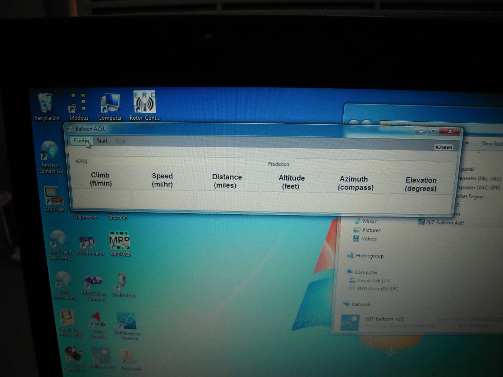

Select Com 4 input
Select Com 7 Output
Input the station ID and node to track
Input the local Latitude and Longitude
Enable both Azimuth and Elevation rotators
Migrated Comments:


September 15th, 2017 at 4:14 pm
I did some novel design for the balloon antenna for 144. 5.6 dbi omni with close to zero fields vertical to eliminate interference with balloon electronics. xmit power was dropped to 80 mw. packets received well over 250 miles.