Making the Heathkit IG-102 Signal Generator Useful
Making the Heathkit IG-102 Signal Generator Useful
While I am very happy with my homebrew 8640jr signal generator, I’ve had this old IG-102 RF Signal Generator from Heathkit hanging around for a decade or so. I was curious what kind of levels it was capable of, so I dragged it out and hooked it up to the scope to investigate a bit.

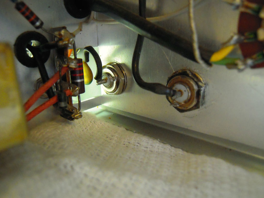
The main problem I have always had with this generator is the connectors on the front for the RF and AF out. They are not commonplace anymore, so replacing them with BNC connectors made sense. Prior to doing this, I always used a coax with alligator clips to connect, which wasn’t very secure.
I found a few panel mount BNC connectors in my junk box, and installed them into the same holes as the original connectors.
Now that I could get decent cables on the generator, I started making measurements. I measured the volts and power into a 50 ohm load on my scope:
| Band | Frequency | Multiplier | mv pp | Power dbm |
| 1 | 95.00 | kc | 45.8 | -23 |
| 1 | 332.00 | kc | 122 | -14 |
| 2 | 302.00 | kc | 79 | -18 |
| 2 | 1.10 | mc | 125 | -14 |
| 3 | 951.00 | kc | 127 | -14 |
| 3 | 3.20 | mc | 231 | -9 |
| 4 | 3.00 | mc | 74 | -19 |
| 4 | 10.99 | mc | 279 | -7 |
| 5 | 9.62 | mc | 37.6 | -24 |
| 5 | 33.00 | mc | 286 | -7 |
| 6 | 31.10 | mc | 18.2 | -30 |
| 6 | 114.00 | mc | 272 | -7 |
Most of the bands have a low output at the low end, but quickly come up to a higher output as you move up the frequency dial.
The bands below 1 mc max out around -14dbm, or 125 mvpp. HF bands are generally capable of -7 dbm into a 50 ohm load. Not bad!
The waveform is generally pretty good, although one or two bands have some distortion. This is not too surprising, given the design of the device.


The modulation is usable, if a little ugly…

At this point, I decided to replace the filter cap, because it was an old electrolytic, and bound to fail at some point.

This piece is not destined to be a collector’s item, so rather than go through hours and hours of work to restuff the original can, I disconnected it (leaving it in place for looks), and mounted the two new caps under the chassis.

While the back was off, I took the opportunity to replace the old power cord, with a safer, 3-wire cord.


Overall, it was a worthwhile couple of hours to upgrade this old generator. It’s a good backup, especially for those times when you need two generators at the same time.
Migrated Comments:
14 Responses to “Making the Heathkit IG-102 Signal Generator Useful”


January 29th, 2016 at 1:07 pm
I pretty much did the same as you but on their other model,using bnc and a audio jack. I don’t like using alligator clips if I don’t have to. the generator is surprisingly accurate for the $$.
June 14th, 2016 at 2:47 pm
Hey wait… with two wires one is neutral not earth ground. if you put a three wire cord in what do you do with the ground ? Wouldn’t it ruin the idea of hot neutral and ground if you make that to chasis ?
June 14th, 2016 at 4:03 pm
Hi Allen. In the IG-102, the neutral is isolated from ground. It goes to one side of the power transformer, while the hot goes to the other side. There is a RF bypass cap from the neutral to ground, but it is high impedance at 60 hz. So I think I am OK with the ground wire hooked to the chassis. I’ve seen no problems with it since doing this. Thanks… Randy WB0SMX
April 22nd, 2018 at 5:57 am
Curious on why you chose 22uf capacitors versus the 20uf.
April 22nd, 2018 at 7:17 am
Hi Mike,
On the older equipment, the electrolytic capacitors had a pretty large specification range (they were not that accurate in the values measured vs the values specified), +/- 20% was common. In modern times, a 20uf capacitor is not common, whereas a 22uf is. You may be able to find a cap specified at 20 uf, but it will typically be more expensive than the 22uf. So I went with the easy, cheap route.
Thanks… Randy WB0SMX
August 20th, 2018 at 5:25 am
The two safety caps next to the power transformer should be changed to the new X2/Y2 disk 0.01 uf safety caps. A full description for replacing them is on the Https:JustRadios.com website, he has lots of old value type parts for tube radios, test equipment, safety caps, and high voltage caps, and resistors. His minimum cost is $20.00 plus shipping, he is in Canada, or get them locally if available. He suggests that the old ceramic disk caps be replaced, because they can cause a shock hazard to the case. The new X2/Y2 disk 0.01 uf safety caps are designed to fail open, not short.
August 22nd, 2019 at 9:31 am
I have the same RF generator, had it since the late 70’s…decided to replace the filter caps and line cord….also installed BNC connectors on front….now I have no internal modulation…any ideas ???
I am not so good with tube technology , thanks in advance for the help
Dwight
August 22nd, 2019 at 11:14 am
Hi Dwight. It’s pretty difficult to troubleshoot from a distance over the internet. Basic suggestions would be to clean the controls with a contact cleaner, and check for wires that may have been broken during disassembly. Also look for and remove solder from bad (cold) solder joints with a grey look to them, rather than bright looking. Then re-solder the connections.
Good luck and 73… Randy wb0smx
September 1st, 2020 at 5:01 pm
Hi Randy
Thanks for the article on this signal generator. I have a similar device. I was looking for some help with the two bottom connectors. I was thinking of replacing them as you did. Now I will.
I get no RF from the two bottom connectors. I do get AF from the connector on the left. I get RF from the two banana jacks. But the higher bands are dead, no rf from them. Any ideas?
Again, thanks for the article, it’s very helpful and gives me encouragement to try to improve my signal generator.
73, Joe W3TTT
September 2nd, 2020 at 10:38 am
Hi Joe. My IG-102 is in storage right now, so I cannot look at it. But I see no banana jacks on my photos in the post. So maybe we have slightly different models. Anyway, if you are getting RF from banana jacks, but not the RF connectors, I would suspect that they should be tied directly together. So I would check the wiring between the two.
Other than that, just checking resistors and capacitors and replacing those out of spec seems to work for most restorers.
Good luck & 73…
Randy WB0SMX
September 10th, 2021 at 1:29 pm
Hi Randy and Joe,
Hope that answering a year after the last post isn’t considered too bad form. There is a version of the 102 (the IG-102S/IGW-102S) that brings out the pre-attenuator RF signal to the front panel banana plugs that Joe mentioned. This was to make it easy to drive, say, a frequency counter with a healthy amplitude at all times, regardless of attenator setting. A nice convenience, to be sure, but it also makes the generator leak RF like (even more of) a sieve than the plain-vanilla 102 does.
— Cheers,
Tom
(Very nice writeup, by the way, Randy. Well done!)
November 3rd, 2021 at 8:21 am
Any way to add a venier drive or whatever to slow the spread on the variable cap.? Still an issue even with a freq. counter.
November 3rd, 2021 at 8:29 am
Correction: I would like to add a vernier or reduction drive on the variable capacitor my IG-102. Any suggestions or alternatives?
November 3rd, 2021 at 9:47 am
Sorry Doug. I have no suggestions for installing a vernier drive on the IG-102. Perhaps installing a smaller variable capacitor in parallel with the original would provide a bandspread function. But I have not looked into that.
Good luck and 73… Randy WB0SMX