Trap Dipole for the Mesa QTH
Trap Dipole for the Mesa QTH
In preparation for the Novice Rig Roundup, I was reminded of my poor state of affairs for low band operation at my Mesa QTH. I had put up a quick 40-meter dipole about 5 or 6 years ago, but it was only about 15 feet off the ground. This did not do a very good job at all, due to the low height and relatively short length.
I had been reading about various antennas, and decided to try out a trap dipole. This would allow me to work 30, 40 and 80 meters with an inverted vee that would easily fit within my backyard of our suburban lot.
30-40-80 meter trap dipole
I had collected several articles about trap dipoles over the years, and was intrigued with the concept of using RG-58 coax wrapped around PVC pipe to form the traps. As I was searching the internet, I came across a site (http://degood.org/coaxtrap/) that used this method to create a multi-band trap dipole for the operators attic. It was short (good for me), and used the interesting coax-type traps.
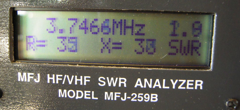
I took down the old 40-meter dipole, and checked the cable, using my MFJ-259B antenna analyzer. The coax was still good, and I measured the length to be about 105′, which turned out to be right at a half-wavelength (accounting for velocity factor of the cable) at 80 meters.
Next, I climbed the tower to about 35 feet. I’d like to say that I chose this height, based on the optimum angle of the inverted Vee, but I would be lying. I just got too tired to climb any higher at that point, so I strapped myself off, and hung the balun for the inverted vee at that point. Hey, it’s 20 feet higher than it was!
This left two wires hinging down the tower, ready to be used at the 30 meter portion of my trap dipole. I started at about 23′-6″ for each leg, and after hoisting the ends up into the air, measured the resonant frequency with my antenna analyzer. It was a little low, so I cut off a little at a time (sometimes an inch, sometimes a quarter inch) until I snuck it up to 10.125 Mhz to match the traps.
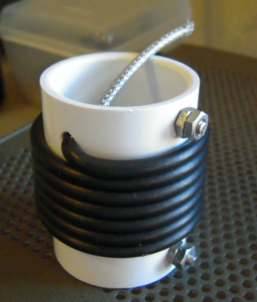
So I borrowed some trap details for the 30 and 40 meter traps that he used, and constructed some for my own use.
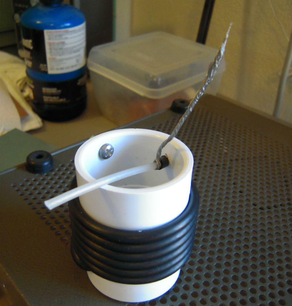
For the 30-meter trap, I used 6-1/2 turns of RG-58 wrapped around a 1-1/4″ PVC coupler from the hardware store. Â Note that this is a coupler, not a piece of pipe. The coupler has a larger outside diameter than the 1-1/4″ size indicated. After wrapping the turns and connecting the center conductor of one side to the braid of the other, I was left with one side with a center conductor loose, and one side with the braid loose. These are the two ends of the trap.
Once the trap resonance was found, I discovered that I could spread and compress the turns to move the resonance point about 100 khz in either direction. Using this method, I put the resonance right at 10.125 MHz. I then used electrical tape to hold the turns in place, checking every couple of wraps to make sure the resonance was still where I wanted it to be.
So I duplicated the first trap and made a second at the same resonant frequency. Then I used the same method to create a couple of 40-meter traps, that I tuned to 7.150 MHz.
Next, I added the two 30-meter traps and about 4 feet of wire on the ends to make up the 40 meter portion of the antenna. This was resonant at too high (7.3 MHz) frequency for me. I think because the original design also had traps for 10, 15 and 20 meters, they would provide some inductive load for the lower bands. Since I didn’t use traps for the upper bands, I needed more wire. So I took off the 4 foot wires and replaced them with 6 foot sections. This was better, as it was below the 40-meter band for resonance.
Again, I cut off a little at a time (6″ twice) and lucked onto 7.150 Mhz resonance with only two cuts.
Now, I added the 40-meter traps and added wire to the end to make up the 80 meter portion. The original design had just over 12 feet, but figuring that again I would need more wire due to not having as many traps, I added 16 feet on each end. It turns out that this put me right in the middle of the 80 meter band, with no cutting necessary.
So there it is. My 30-40-80 meter trap dipole. I found that the resistance and reactance flutters maybe 3-5 ohms while I watch it on my analyzer. Not enough to significantly affect SWR, but enough to test my patience while testing it. I think maybe the balun is too close to the metal tower leg, and the wind wriggles it around a bit, changing the impedance slightly. I may want to move it out away from the tower leg on a pole a foot or two.
It is fairly noisy in town, picking up all of the plasma TVs (mine included), but has much stronger signals than my Cushcraft A4 mounted ten feet above it.
We’ll see how it does in the Novice Rig Roundup.
Migrated Comments:


July 11th, 2021 at 8:10 am
JUST CHANGING THE WIRE FOR RG-8X COAX IN BAZOOKA FASHION AT CENTER AND THE ANTENA IS EVEN BETTER PERFORMER LOW NOISE FLOOR AND OUTSTANDING OUTPUT ON ALL 3 BANDS