HW-16 Board Restoration (Part 2)
HW-16 Board Restoration (Part 2)
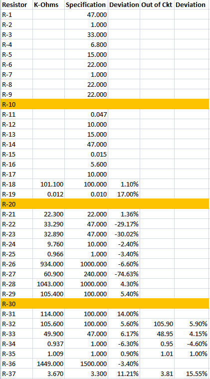
Now that the foil side of the board was fairly clean, I began checking the value of the resistors on the board. I made a chart with the expected values, and the measured in-circuit values. Then I put a column in for percent of deviation. I realize that in some cases the readings could be lower, due to interaction of other parts in the circuit. But this gave a quick view of those that definitely needed to be replaced, as they were reading too high, even in circuit.
After going for a while, I realized that I would be happier just replacing all of the resistors on the board with new ones. I really needed to lift leads to check them effectively, anyway.
So, I started in the upper left corner and methodically started removing resistors, measuring them (and adding the out-of-circuit measurements to the resistor spreadsheet), and replacing them. I used the 1%, 1-watt resistors mentioned a few posts back ( Resistor Color Codes ). The new 1-watt resistors are pretty much the same physical size as the old half-watt resistors they were mostly replacing. So they look reasonable mounted to the board. Modern 1/2-watt resistors would have been tiny, and looked really out of place. The bad news is that the new resistors have that odd color code, but I’ll pack a note in with the rig when I’m done, explaining the difference to future hams that may end up working on this some day.
Here is a view from the initial cleaning stage of the top of the board before any resistors were replaced:
And here is the board with the resistors on the left replaced (the new resistors all have a blue substrate):


Comments
Post a Comment