8640jr First 3 Stages
8640jr First 3 Stages
I finally got some time to work on the 8640jr Signal Generator Project. I decided to put the VFO and the first two amplifiers inside an aluminum box. Why? I’m hoping it will help the frequency circuits temperature-stabilize, and provide a way to isolate the sensitive frequency determining components from the effects of a hand getting near them and shifting the frequency while operating it.
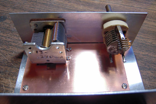
I started by mounting the blank pc board in the enclosure. This gave me a guide as to the height and position of the main and bandspread tuning caps:
The main tuning cap was one I picked up from Antique Radio Supply, in Tempe, AZ. Their website lets you order for the will-call window, if you are local. The bandspread cap was a hamfest special.
Once the caps were mounted, I now had a guide as to where to place the pads for the various components. I knew I had to avoid the areas directly under the tuning caps. I drew up the component placement guide in Visio, because it allows me to print out an exact size copy on my printer. After laying a copy of the layout on the board, I was able to use a center-punch to mark where each pad would go for the first stage.
After laying out the components for the Hartley Oscillator, I was able to scope the output of Q1 at the Source lead.
I continued on with the Q2 Follower stage.
The output of Q2 on the Source lead is about 1.5 vpp. There is some voltage loss, but the stage is meant to isolate the high impedance output of the oscillator from effects down the string.
Finally, I assembled the third stage, a 2n3904 buffer amplifier.
The output of this stage rolls off a little bit on the high end. I hope to end up with enough gain in the end product that I can have a variable attenuator to dial in the signal level on a meter, much like the old URM-25 signal generator that I learned on.
Migrated Comments:


August 15th, 2013 at 7:24 pm
Hello Sir
Yesterday I also ‘ve just finished build 3 stages of this 8640jr.
I just check the output waveform of my Q1 ( BF245C )source, it’s pretty much same as yours, good sine wave, but I didn’t note the voltage.
At Q2 ( BF245C ) source, I notice some distortion on peak waveform.
Then at the output of T1, I attached 0.1u coupling cap then terminated to a 50 Ohm R, the wave form across this R is bad.
I never succeed obtain a clean sinewave from any buffer that I’ve made ( ex. hycas signal generator from qrp.pops.net ). Do you have any suggestions to obtain a clean sine wave after T1 ? before last attemp put a LPF ( Fco=30MHz ) after T1.
Thanks.
Indra Sungkono