900Mhz Experiment
900Mhz Experiment
I happened to have an old 902 – 926 Mhz cordless phone laying around the shack. Since this is in the range of the 33cm ham band (902 -928 mhz), I thought it might be cool to make a sort of portable autopatch with it. It has full duplex capabilities, with the base transmitting in the 902 mhz region, and the handset transmitting in the 926mhz region. Both use narrow band FM.
Here is what the end result looks like:
The idea of the project is to use a cellphone as the phone carrier end, and the 900 mhz cordess phone as the remote radio end.
The first step was to range test the 900 mhz cordless phone. Since this had to be outside, where there was little interference from walls, I had to devise a scheme to provide telephone carrier current in order to test it without actually hooking it to a phone line. By putting a 9-volt battery in series with a 220-ohm resistor, all in series with one leg of the phone line, I was able to connect an old ITT telephone and the cordless base together.
Since the base was for operation at 9-volts, I rigged up a test cable to plug in to my accessory socket in my truck to power the base from. The test cable simply has 2 1N4001 diodes in series with the hot lead, to drop about 1.4 volts from the nominal 12.6 or so. This put it in a range the base could handle, without digging around to find a 9-volt regulator.
So we end up with something like this. When I speak into the telephone, my voice comes out of the cordless phone, and vice-verse.
So, I had the grandkids walk down the street with the handset, while I stayed on the telephone end. They were able to walk down all the way to the busy street (which I didn’t want them to cross) and still get service.
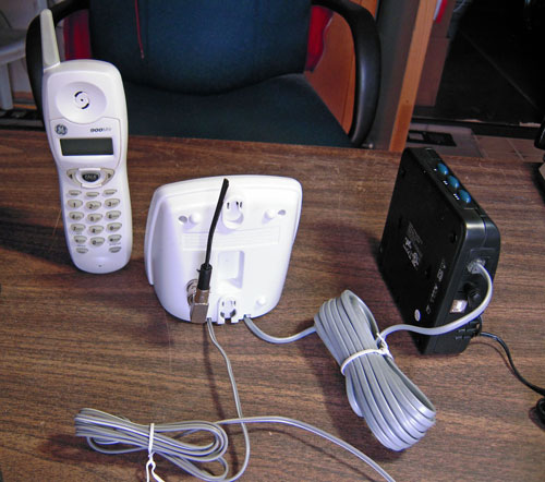
Next, I replaced the small 3″ internal antenna in the base with a bnc connector.
And here is a view of the BNC connector from the outside.
Once that was done, I made a really simple monopole antenna that just replaces the internal antenna, without any radials. Range was about the same before and after the mod.
Then I decided to replace the 600 ma-hour handset batteries with some more robust 2000ma-hour ones, to extend the time between charges.
I have not had to charge the handset, after the initial charge a week ago…
So next, we built a 900-mhz yagi for the base unit. This was modeled after the WA5VJB “Cheap Yagi” design. It was orginally published in the Central States VHF Society Conference Proceedings for 1994. W0FMS has a nice website that has re-documented the design.
We used a Dremel tool with a reinforced fiber cutting blade to cut the elements. Most of them are from some brazing rod that I had laying around, and a few were from some brass rod I picked up at ACE Hardware.
Here are all of the elements cut to size…
The elements were fastened to a 1x2x40 inch piece of oak trim that I had in the garage. Some #6 nuts were drilled out to allow the rods to pass through them, then after careful centering, they were soldered to the nuts.
The Driven element is a hairpin feed… very simple to make and match.
So here is the finished product:
It has one reflector, one driven element and 8 directors for a gain of about 12 dbi.
Testing involved leaving the base inside, with its monopole antenna, and attaching the yagi to my Kenwood TH-F6 handheld. Tuning to the 902mhz frequency range, I can get a carrier on the handheld. The S-meter definitely shows a null when broadside to the direction of the base, and shows some forward gain. I haven’t made precise measurements yet.
I got a note from Greg (VE3FAX) gently chastising me for not providing more testing details. Â Thanks for the reminder, Greg! Anyway, no the project did not die. We did not do any extremely long distance tests, as that was not our purpose. We did take the stuff up to our ranch in northern Arizona, and ran a reliability test over about a half-mile range, through juniper and pinyon pine trees. We were attempting to extend the cell phone signal from where it was available down into our valley, which had zero cellphone coverage. The contraption worked perfectly for that purpose. Because the first test site was in the open and easily visible from the dirt road that leads to our place, we decided to look elsewhere for a final installation spot. We found a spot up the hill from our cabin, only about 300 feet away. Once we mounted the equipment there, we had perfect telephone service down to the cabin whenever we were on site. We mounted the “repeater” in a couple of weatherproof boxes, along with a marine battery and a 20-watt solar panel charging system. When we arrive at the site for a visit, I hike up the 300 feet to the repeater, place my cellphone in one of the boxes, and plug it into the charger. Then we turn everything on, and have phone service where we had none before. Sort of like a private autopatch.
Migrated Comments:


October 12th, 2012 at 12:42 pm
Thats it? Your going to leave us hanging? no further testing or range reports or did the project die? Fun project but killer for my 902SSB ops…fun info…thanks…great idea on the POTs handset..
73 Greg
October 26th, 2012 at 3:46 am
Thanks for the update Randy! …and the great web site
73
Greg
VE3FAX